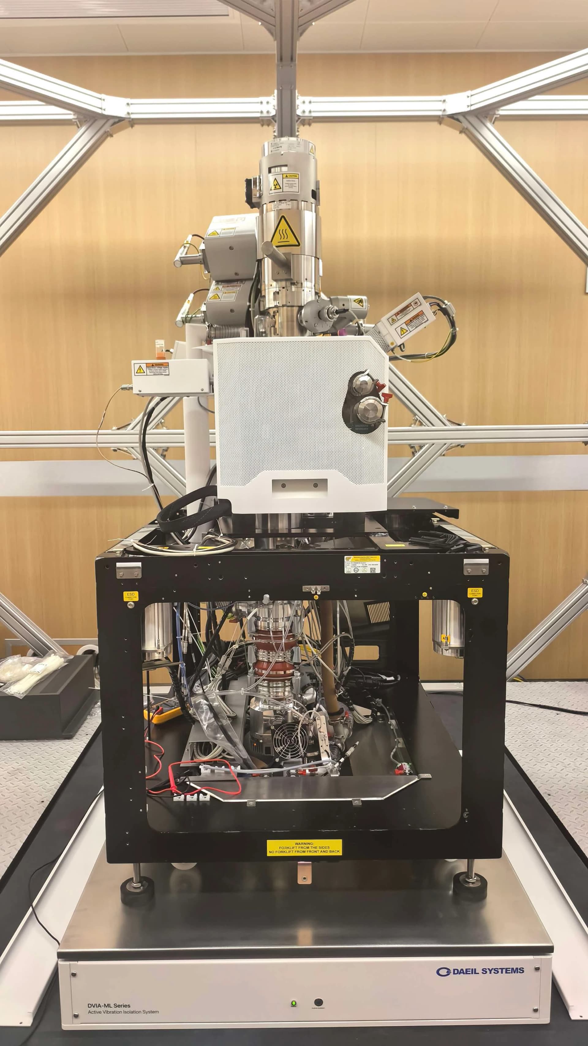
RAITH Voyager DVIA-ML1000 Installation Report
Contents
Overview
Following the installation of DVIA-ML1000 at Suzhou, tuning and vibration measurement were performed.
Vibration measurement was conducted with the equipment in the Idle state.
Data is represented in Autospectrum format and reference material on the vibration level is provided.
Vibration Isolation System Information
Model: DVIA-ML1000
Serial Number: 260422R1-2
Engineer
Taehun Kim · DAEIL SYSTEMS
Tuning Date
2026.08.28
End User
Suzhou Dingxin Photoelectric
Number of Tuning Trial
2nd
Site
Suzhou
Equipment
Manufacturer: RAITH
Equipment: Electron Beam Lithography system
Model: Voyager
Vibration Specification
Horizontal
| Frequency [Hz] | Allowable [µm/s RMS] |
|---|---|
| 1 | 0.8 |
| 16 | 0.8 |
| 16 | 1 |
| 100 | 1 |
Vertical
| Frequency [Hz] | Allowable [µm/s RMS] |
|---|---|
| 1 | 0.8 |
| 16 | 0.8 |
| 16 | 1 |
| 100 | 1 |
Equipment Condition
Idle
Tuning Request
Conclusion
Vibration measurements were performed at two positions — the installation floor and the top surface of the DVIA-ML1000 active vibration isolation system — and evaluated against the criteria defined in Section 9.
At the floor level, all three axes (vertical, left-to-right, and front-to-back) exceeded the specified criteria, indicating that the ambient vibration environment at the installation site is not adequate to support the operating requirements of the equipment.
A second tuning iteration was carried out to optimize the control parameters for the installed configuration. Following this adjustment, all three axes measured on the isolation system satisfy the specified criteria, confirming that the DVIA-ML1000 provides sufficient attenuation to bring the equipment environment into compliance.
It should be noted that a localized response was observed in the 9–10 Hz range on the isolated surface. Based on its frequency characteristics and axis behavior, this response is presumed to originate from mechanical interference between the equipment and adjacent structures or connected utilities rather than from the isolation system itself.
Although the measured levels remain within the specified criteria and no impact on equipment operation is expected, it is recommended that the routing of connected lines and any physical contact points around the isolated platform be reviewed to eliminate the potential transmission path.
Measurement Summary
| Measurement Point | Vibration Specifications | Axis | Result | |
|---|---|---|---|---|
| Floor | DVIA-ML1000 | |||
| 1. Floor 2. DVIA-ML1000 | See Section 9 | Vertical | ✗ FAIL | ✓ PASS |
| Left to Right | ✗ FAIL | ✓ PASS | ||
| Front to Back | ✗ FAIL | ✓ PASS | ||
Measurement Data Obtained via UI Program
Vertical
Vertical — Autospectrum
Left to Right
Left to Right — Autospectrum
Front to Back
Front to Back — Autospectrum
Installation Photo
Equipment
Reference
The table below classifies vibration levels based on IEST-RP-CC012.2.
¹ As measured in one-third octave bands of frequency over the frequency 8 to 80 Hz (VC-A and VC-B) or 1 to 80 Hz (VC-C through VC-G).
² The detail size refers to the width in the case of microelectronics fabrication, the particle (cell) size in the case of medical and pharmaceutical research, etc. It is not relevant to imaging associated with probe technologies, AFMs, and nanotechnology.
The information given in this table is for guidance only. In most instances, it is recommended that the advice of someone knowledgeable about applications and vibration requirements of the equipment and processes be sought.
Share this Case Study
Case Study Information
Related Case Studies
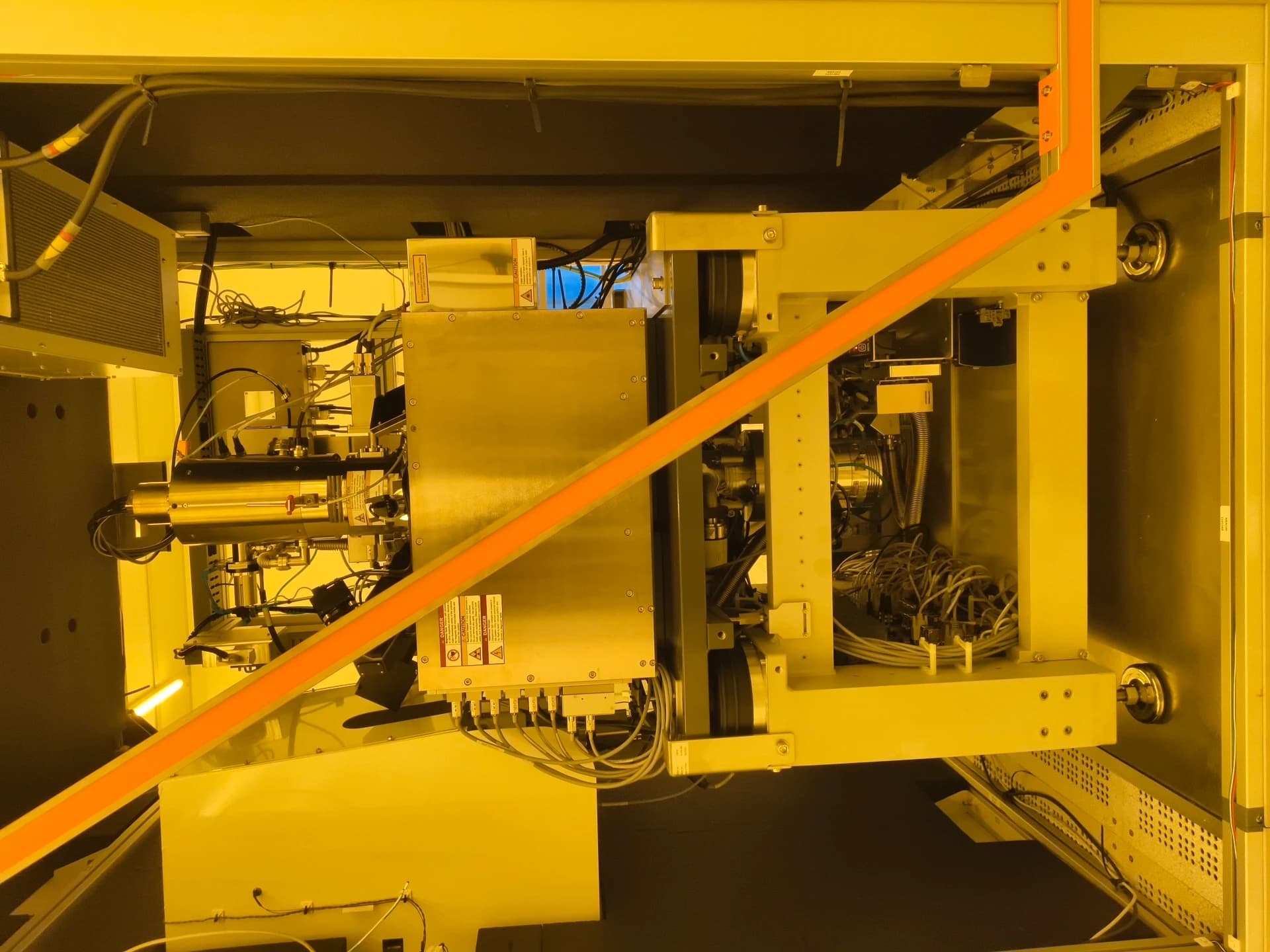
RAITH Voyager E-Beam DVIA-ML1000 Installation Report
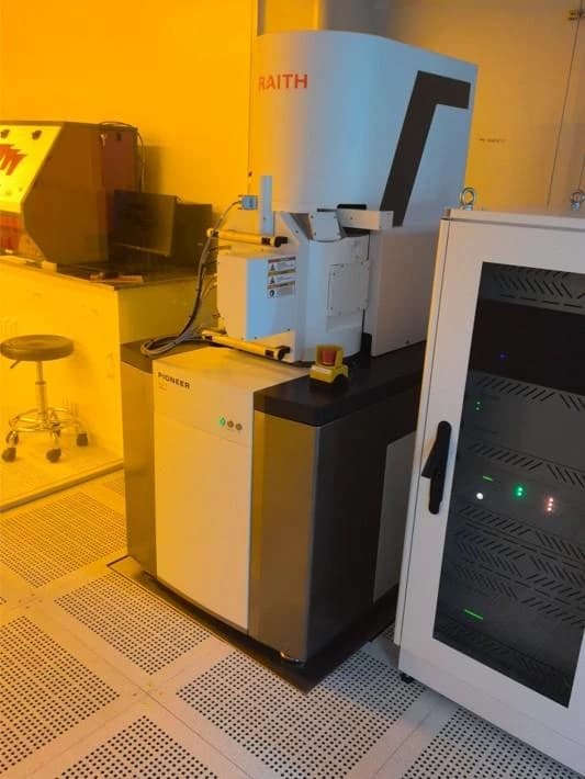
Hubei University of Technology RAITH Electron Beam Lithography Pioneer Two DVIA-ML1000 Installation Report