Feedforward Control: Cancelling Vibration Before It Arrives
Feedforward control measures a disturbance and cancels it before it affects the output — how it works, its limits, and its role in active vibration isolation.
Last updated
1.What Is Feedforward Control?
Feedforward control is a control strategy in which the disturbance itself is measured and counteracted before it can affect the output, instead of waiting for an error to appear and then correcting it. A feedback controller watches the quantity it is supposed to protect and reacts to deviations after the fact; a feedforward controller watches the thing that causes the deviations and moves preemptively. The distinction sounds subtle written down, but it changes what a control system can achieve: a disturbance that is cancelled on the way in never has to be recovered from at all.
The everyday version is familiar to anyone who has heated a room in winter. A thermostat is pure feedback: it waits for the temperature to drop, notices the error, and only then adds heat — by which time the room is already cold. A person who turns the heater up the moment the door opens to the snow is running feedforward: they measured the disturbance — cold air is about to pour in — and applied the correction before the temperature ever moved. Neither approach is complete by itself, a point this note returns to, but the anticipatory one removes most of the excursion the reactive one would have had to chase.
One disambiguation before going further. "Feedforward" also names an architecture of artificial neural networks — networks whose connections run only from input toward output — and a management technique that replaces criticism of past work with suggestions for future work. Those usages share an etymology and nothing else. This note covers feedforward in control systems, and specifically one of its most demanding industrial applications: measuring floor vibration and cancelling it before it reaches a precision instrument. Everything that follows applies to feedforward controllers in general, but the examples come from vibration isolation, where the technique is pushed hard.
2.Feedback vs. Feedforward: A Structural Difference
Feedback and feedforward differ not in degree but in topology. A feedback controller closes a loop: it measures the very output it is protecting, compares it with the target, and drives an actuator to shrink the difference. The great virtue of this arrangement is that it is comprehensive — the error signal contains the effect of every disturbance from every source, whether or not the designer anticipated it. The cost is built into the same wiring. Feedback can only respond to an error that already exists, and because its corrective action re-enters its own measurement, the loop can turn on itself: at frequencies where accumulated phase lag rotates a cancelling force into a reinforcing one, too much gain means oscillation. Stability, not ambition, caps how hard feedback may push.
A feedforward controller never touches the output at all. It measures the disturbance at its source, passes that measurement through a model of how the disturbance propagates to the output, and injects an equal-and-opposite correction. With respect to the protected variable the path is open-loop: nothing the controller does re-enters its own input, so there is no oscillation mechanism and no stability ceiling — the gain can be set as aggressively as the model deserves. The symmetry of strengths and weaknesses is exact. Feedforward is blind to any disturbance it does not measure, and it is only as good as its model of the propagation path; a mismatch destabilizes nothing, but the fraction of the disturbance the model got wrong sails through untouched.
3.How Feedforward Works in Vibration Isolation
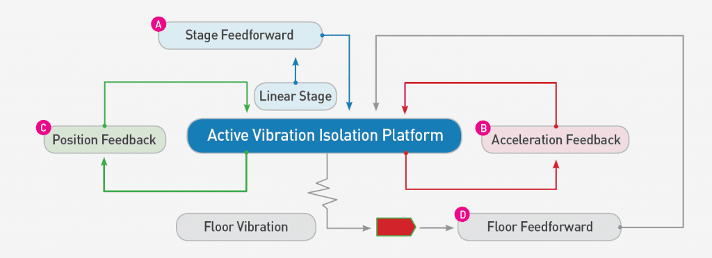
In an active vibration isolation platform the abstraction becomes concrete hardware. The disturbance is ground vibration — foot traffic, HVAC plant, road traffic, the slow sway of the building itself — and the output to be protected is the motion of the isolated payload carrying the instrument. Feedforward sensors therefore mount on the floor, upstream of the isolators, where they read the incoming vibration before it has had any chance to propagate through the spring path into the platform. That head start is the entire premise: the isolators transmit ground motion only through their slow, low-pass mechanical dynamics, while the measurement reaches the controller electronically almost instantly — giving the correction an effective lead over the disturbance it must meet.
The controller passes the floor signal through an identified model of the transfer path — the measured dynamics from floor motion, through the isolators, to payload response — and commands the actuators to apply the force that will meet the arriving disturbance with its mirror image. When the identification is good, the two largely annul each other, and a large share of the ground input never registers on the payload at all. Nothing had to go wrong first; no error was ever produced for a feedback loop to chase. This is the sense in which feedforward cancels vibration before it arrives, and it is why the technique is prized exactly where feedback is weakest — at low frequency, where waiting for an error costs the most.
4.Why Feedforward Alone Is Not Enough
The same topology that frees feedforward from stability limits also draws a hard boundary around what it can do. A floor sensor sees the floor; it cannot, even in principle, see a disturbance that originates on the payload itself. A pump running on the payload, an operator resting a hand on the enclosure — disturbances like these never cross the floor sensors, so no feedforward gain, however aggressive, touches them. And within its own territory the cancellation is only as exact as the identified transfer path. Payloads get rearranged, air pressures drift, structural modes move with load; each mismatch between model and reality converts a slice of the measured disturbance into residual motion.
This is why a serious active isolation system runs a second loop. Feedback sensors on the isolated platform measure the residual motion the payload actually experiences — whatever leaked past the feedforward path, plus everything that was born on the platform — and drive the actuators to null it. In short: feedforward pre-empts the ground input it can see, feedback catches everything it cannot. How that feedback loop is engineered — the sensing chain, the stability margins, the notch filters that tame structural resonances — is the subject of our companion note on how active vibration cancellation works; here it is enough to see that neither loop can substitute for the other.
5.What Makes Good Feedforward Hard in Practice
The concept fits in a sentence; the performance lives in the execution. The first difficulty is the model. The floor-to-payload transfer path has to be identified from measurements on the actual installed system and then tuned, because the correction is injected blind — feedforward never gets to check its own work against the output. Closely related is coherence: the scheme assumes the vibration at the floor sensor is a faithful predictor of what will arrive at the payload. Where the floor moves differently at different points, or a sensor sits far from the true entry path, the correlation between what is measured and what arrives degrades, and the achievable cancellation degrades with it. Sensor placement is therefore an engineering decision, not an afterthought.
The second difficulty is time. The whole advantage of feedforward is arriving before the disturbance does, and that advantage is spent in milliseconds. Every stage of the electronic path — sensing, filtering, computation, actuation — adds delay, and a pure delay T contributes 360 × f × T degrees of phase error at frequency f. A correction that arrives late is a correction pointed in the wrong direction: as the phase error grows the cancellation collapses, and past a point the "correction" adds energy instead of removing it. Our companion note on how active vibration cancellation works walks through the phase budget of a real signal chain; here the point is simply that latency is the currency feedforward spends, and there is very little of it to spend.
6.Feedforward in DVIA Active Isolation Systems
DAEIL SYSTEMS' DVIA active platforms run feedback and feedforward concurrently, as two halves of one controller. The payoff shows exactly where the theory predicts it should: at low frequency. Building vibration concentrates its energy below roughly 20 Hz, much of it below 5 Hz, and a passive pneumatic isolator — natural frequency 1.2 to 3.0 Hz — amplifies motion near resonance and isolates well only above roughly 5 to 10 Hz. DVIA systems hold active control from 0.5 Hz up to 200 Hz depending on model, in all six degrees of freedom; the DVIA-ML, the electron-microscope series, removes up to 80–90% of floor vibration at 1 Hz and 90% or more from 2 Hz upward — performance delivered precisely in the band where the passive support beneath a microscope would otherwise be amplifying.
The architecture scales across the lineup: custom DVIA-ML platforms built for specific instruments such as the Krios G4, Glacios 2, and JEM-F200; the base-type DVIA-MB, where the isolator forms the instrument's own base; modular DVIA-ULF point-support units for SEM, TEM, and AFM setups; the tabletop DVIA-T; and the active-pneumatic DVIA-P for cleanroom and semiconductor inspection tools, which applies the same closed-loop principle through accelerometers and pneumatic servo actuators. Behind them stands a vibration isolation specialist working since 1984, with more than 1,000 published installation case studies across SEM, TEM, AFM, and semiconductor metrology. If this note began with a definition, it ends with the definition doing useful work: the model-by-model comparison on our active vibration isolation hub reads differently once you know that behind every isolation figure stand two loops — one cancelling what can be seen coming, the other absorbing everything else.
