Vibration Sensors: Accelerometers, Geophones, and How to Choose
How vibration sensors work — piezoelectric and MEMS accelerometers, geophones, non-contact probes — and how to choose one by frequency band and noise floor.
Last updated
1.What Is a Vibration Sensor?
A vibration sensor is a transducer that converts mechanical motion into an electrical signal an instrument can record and analyze. Behind that one-line definition sits a choice that shapes everything else: the same motion can be described as displacement, velocity, or acceleration, and the three are not interchangeable in practice. For a sinusoidal vibration they are locked together by frequency — each differentiation multiplies amplitude by 2πf — so a floor moving 1 μm at 1 Hz has a velocity of about 6.3 μm/s and an acceleration of only 40 μm/s², roughly four millionths of gravity. The identical displacement at 100 Hz produces an acceleration ten thousand times larger.
That scaling is why sensor choice is, before anything else, a frequency-band decision. At high frequencies acceleration amplitudes are large and easy to measure, which favors accelerometers; at low frequencies acceleration collapses toward nothing while displacement and velocity remain measurable, which favors velocity and displacement sensing. Every sensor family on the market is, at bottom, a proof mass or a probe optimized to read one of the three quantities over one band with one noise floor. No universal vibration sensor exists — only sensible matches between the quantity measured, the band of interest, and the smallest signal that must be resolved.
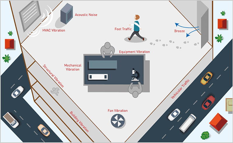
This note surveys the main families — piezoelectric and MEMS accelerometers, geophones and seismometers, and the non-contact optical and eddy-current instruments — and closes with the application where sensing is pushed hardest: the closed-loop active isolation platforms that protect electron microscopes and semiconductor metrology tools from the floor they stand on.
2.Piezoelectric Accelerometers: The Industrial Workhorse
The piezoelectric accelerometer is the industrial workhorse of vibration measurement. Inside the housing, a small proof mass presses on a piezoelectric crystal; when the case accelerates, the inertial force of the mass — force equals mass times acceleration — strains the crystal, which responds by generating an electric charge proportional to that acceleration. The mechanism has no sliding parts and no electronics in the signal path at all, which is why these sensors are famously rugged: they survive shock, run from a few hertz to tens of kilohertz, span enormous dynamic ranges, and tolerate the temperatures found on gearboxes, turbines, and engine casings. For machinery monitoring, modal testing, and general structural work, they are the default answer.
Two electrical interfaces divide the family. A charge-mode accelerometer outputs the crystal's charge directly and relies on an external charge amplifier; the arrangement demands low-noise cable and careful handling but keeps all electronics away from the sensor, so it operates at temperatures that would destroy semiconductors. An IEPE accelerometer — integrated electronics piezoelectric — builds a tiny impedance converter into the housing, powered by a constant current over the same coaxial cable that carries the signal back as a low-impedance voltage. Ordinary cable, simple wiring, and stable behavior have made IEPE the dominant choice wherever the environment allows it.
The weakness is the low end. A piezoelectric element cannot hold charge indefinitely, so the response is inherently AC-coupled and rolls off below a corner frequency; there is no DC response at all. Worse, physics works against the measurement in the same band: for a fixed displacement, acceleration amplitude falls with the square of frequency, so the sub-hertz floor motion that matters most to a precision instrument generates an acceleration signal that sinks beneath the electronic noise. Measuring the slow, small vibrations of a building calls for a different transducer — which is where velocity sensors come in.
3.MEMS and Capacitive Accelerometers: Small, Cheap, DC-Capable
A MEMS accelerometer replaces the crystal with a micromachined silicon structure: a proof mass suspended on flexures, its position read capacitively from the changing gap between interleaved electrodes. Because the readout senses position rather than strain-generated charge, the response extends to DC — a MEMS device measures constant acceleration, including gravity itself, which is why the same chip serves as an inclinometer. Batch fabrication makes the parts small, low-power, and inexpensive, and they have carried vibration sensing into places piezoelectric sensors never reached: wireless condition-monitoring nodes scattered across a plant, tilt measurement, impact detection, and the phone in your pocket.
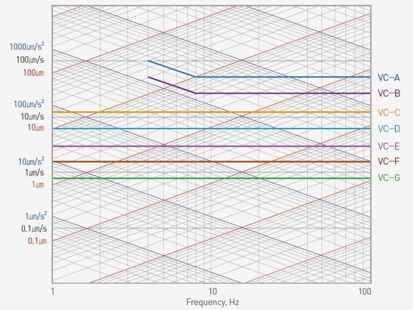
The trade-off is the noise floor. Capacitive readout of a milligram-scale mass cannot match the signal-to-noise of a large seismic proof mass, and typical MEMS parts show noise levels far above the few micrometers per second RMS in which vibration criteria for precision facilities are written. Force-balance and servo-type designs close some of the gap, at a corresponding price. The practical rule: MEMS excels at machine-level vibration, tilt, and gross motion, but a floor survey for an electron microscope site — resolving VC-D or VC-E levels — is beyond ordinary MEMS devices and belongs to seismic-grade sensors.
4.Geophones and Seismometers: Why Velocity Matters
Where accelerometers give up, velocity sensing takes over. A geophone works by electromagnetic induction: a coil hangs on a compliant suspension in the field of a permanent magnet fixed to the housing, and once the driving frequency exceeds the suspension's natural frequency, inertia keeps the suspended coil nearly motionless while the housing — and the magnet with it — moves with the ground. The voltage induced by that relative motion is directly proportional to velocity, with a flat sensitivity of typically 2.55 V/in/s, about 100.4 V/m/s, in seismic-grade geophones. The transducer is self-generating — no power supply, a low source impedance, and noise that can be kept extraordinarily low — and seismometers push the same principle to still lower frequencies with softer suspensions and feedback electronics for observatory-grade work.
Below the natural frequency the output rolls off steeply, but low-noise amplification combined with DSP inverse filtering can restore usable sensing down to about 0.3 Hz. How that two-stage compensation works — and what it costs in phase budget and self-noise — is covered step by step in our companion note on how active vibration cancellation works.
Velocity is also the natural language of building vibration. Structural motion concentrates below about 20 Hz, and the generic vibration criterion (VC) curves that govern precision facilities are defined as limits on RMS velocity in one-third-octave bands — the strictest common grades reaching down to a few micrometers per second, 3.12 μm/s RMS at VC-E. A velocity sensor therefore reads directly in the criterion's own units, with no error-amplifying integration of an acceleration signal. It is no accident that floor surveys and seismic-grade instrumentation are built around geophones; our vibration criteria note tabulates the full VC family.
5.Non-Contact Sensors: Measuring Without Touching
Sometimes the sensor cannot touch the target. A rotating shaft offers no stationary mounting point; a surface may be too hot, too delicate, or inside a vacuum; and a very light structure changes its behavior the moment a sensor's mass is added to it. Eddy-current probes answer the rotating-machinery case: a coil driven at high frequency induces currents in a conductive target, and the gap between probe and surface modulates the coil's impedance, yielding a non-contact displacement measurement that is standard practice for monitoring shaft vibration in turbomachinery. Capacitive displacement probes apply the same idea electrostatically, resolving nanometer-scale gaps in precision mechanics.
Optical instruments go further. A laser Doppler vibrometer reads the frequency shift of light reflected from a moving surface and returns its velocity with no contact at all, while interferometric techniques resolve displacement down to fractions of a nanometer. They impose no mass loading, reach targets behind windows, and can scan an entire surface point by point — at the price of cost, alignment, and the need for optical access. For the vast majority of installations, though, a contact inertial sensor mounted to the structure remains the practical instrument, and the selection question returns to matching its band and noise floor to the job.
6.Choosing a Sensor — and How Active Isolation Puts Them to Work
Choosing a vibration sensor reduces to three questions. Which frequency band carries the information — machinery harmonics at hundreds of hertz, or building sway below 5 Hz? How small is the smallest signal that must be resolved, and does the sensor's noise floor sit safely beneath it — a floor survey against VC-E, for instance, must resolve a few micrometers per second RMS? And what does the environment impose: temperature, magnetic fields, vacuum compatibility, cleanroom rules, the mass the structure can accept? Answer those three and the taxonomy above collapses to one or two candidates almost immediately.
The most demanding application of all closes the loop. An active vibration isolation platform is, at its core, a sensor system operating in real time: geophones on the isolated payload measure residual motion for the feedback loop, sensors on the floor measure incoming ground vibration for the feedforward path, and a DSP converts both into actuator forces that cancel the disturbance — a chain our companion note on how active vibration cancellation works follows stage by stage. Every property discussed in this note is stressed simultaneously: sub-hertz bandwidth, self-noise low enough that the sensor never becomes the disturbance, and phase behavior clean enough to keep the loop stable.
This is the discipline DAEIL SYSTEMS has practiced since 1984, with more than 1,000 published installation case studies across SEM, TEM, AFM, and semiconductor metrology. DVIA active systems control all six degrees of freedom from 0.5 Hz up to 200 Hz depending on model; the DVIA-ML for electron microscopes removes up to 80–90% of floor vibration at 1 Hz and 90% or more from 2 Hz upward, while the cleanroom-oriented DVIA-P applies the same closed-loop principle with accelerometers and pneumatic servo actuators — sensor selection matched to the environment, exactly as above. The path to the right platform starts with a measured floor survey compared against the VC criteria, not with a catalog; the full model lineup is compared on our active vibration isolation systems hub.
