Vibration Isolation for Semiconductor Metrology and Wafer Inspection
Why metrology tools are vibration-limited, which VC criteria apply, and how active-pneumatic and base-type platforms hold CD-SEM, inspection, and analysis tools steady.
Last updated
1.Why Are Metrology and Inspection Tools the Most Vibration-Sensitive Equipment in the Fab?
Process tools transform the wafer; metrology and inspection tools measure it — and measurement is where vibration becomes visible. A CD-SEM measuring gate line widths, a defect-review SEM (DR-SEM) re-imaging a flagged defect, an automated AFM profiling a film surface: each must resolve details far smaller than the motion of an ordinary factory floor. The same holds for photomask qualification and repair, X-ray metrology and defect inspection, non-contact 3D surface metrology, and thin-film thickness measurement. Floor vibration reaching a tool like this does not break anything; it quietly widens the error bars on every measurement the fab depends on.
The vibration criterion (VC) tables used to specify these environments make the sensitivity explicit. Equipment resolving 1–3 μm details is served by a VC-C environment; at 0.1–0.3 μm the requirement tightens to VC-D, the class that covers many electron microscopes; below 0.1 μm — the regime of E-Beam systems working at nanometer scales — VC-E applies. By contrast, semiconductor probe test equipment is usually adequate at a 'residential' level of about 200 μm/s — a factor of roughly sixty above the strictest semiconductor criterion, inside the same building.
Vibration corrupts a measurement through two doors. The first is blur: relative motion between the electron column or optics and the wafer during acquisition smears the image and inflates measurement uncertainty. The second is settling: automated tools step their motorized stages from site to site, and residual oscillation after each move delays the next acquisition. Blur costs accuracy and repeatability; settling costs throughput. Any serious approach to wafer inspection vibration isolation has to close both doors.
2.Which VC Criterion Applies to Which Semiconductor Tool?
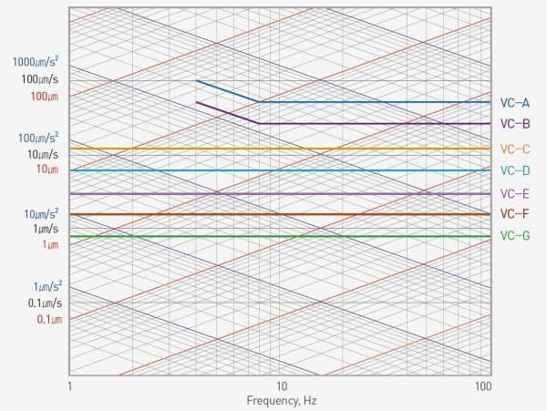
The VC (vibration criterion) curves, developed by Colin Gordon and his associates, are the de facto worldwide standard for specifying floors that must support vibration-sensitive equipment. Each curve is a limit on root-mean-square velocity measured in one-third octave bands — over 8 to 80 Hz for VC-A and VC-B, and over 1 to 80 Hz for VC-C through VC-G. A floor 'meets VC-D' when its measured spectrum stays below the VC-D line in every band.
For semiconductor work the ladder reads as follows. VC-A (50 μm/s) is adequate for optical microscopes to 400x and for proximity and projection aligners. VC-B (25 μm/s) is appropriate for inspection and lithography equipment, including steppers, to 3 μm line widths. VC-C (12.5 μm/s) is the standard for optical microscopes to 1000x and for lithography and inspection equipment to 1 μm detail size, including moderately sensitive electron microscopes, as well as TFT-LCD stepper/scanner processes. VC-D (6.25 μm/s) suits demanding equipment — many electron microscopes (SEMs and TEMs) and E-Beam systems. VC-E (3.12 μm/s) is a challenging criterion assumed adequate for the most demanding sensitive systems, including E-Beam lithography working at nanometer scales. VC-F and VC-G exist for evaluating extremely quiet research spaces and are not recommended as design criteria.
One caution: the table is guidance, not gospel. The binding document is always the tool vendor's own installation specification, and the criteria's own notes recommend consulting someone knowledgeable about the equipment and its process. The definitions and the complete table are covered in the Generic Vibration Criteria technical note in this Support section.
3.Why Are Fab Floors Harder Than They Look?
On paper a fab is the best possible home for sensitive equipment: thick slabs, deep foundations, structures engineered with vibration in mind. In practice, three things work against the metrology bay. First, machinery that never stops: subfab pumps, air handlers, and exhaust fans feed continuous vibration into the structure. Second, many tools do not sit on the slab at all but on raised access floors and support structures, and every interface between tool and slab adds compliance. Third, and least visible, the building itself moves at low frequency: wind loading, heavy traffic nearby, and the structure's own dynamics concentrate energy in the band below 5 Hz.
That low-frequency component is what defeats the conventional remedy. A passive pneumatic isolator is a spring with a natural frequency of 1.2–3.0 Hz: near that resonance it amplifies vibration rather than reducing it, and it isolates effectively only above roughly 5–10 Hz. The VC framework itself acknowledges the problem — VC-C through VC-G are measured down to 1 Hz, squarely inside the band where a passive mount either transmits or amplifies.
There is also a disturbance no floor survey can catch: the tool's own stage. Each time a wafer-metrology stage accelerates with real mass on board, reaction forces act on the tool base and displacement follows. A site can therefore pass its vibration survey while the tool still fails its repeatability spec: the dominant disturbance is generated inside the machine. Solving it requires an isolation system that is actively stiff and can be told, in real time, what the stage is doing — the subject of the next section.
4.How Does Active-Pneumatic Isolation Work? Inside the DVIA-P
Most active isolators cancel vibration with electromagnetic actuators. The DVIA-P series takes a different route, built for fab conditions: extremely sensitive accelerometers detect vibration, a digital controller computes the response, and pneumatic servo valve actuators — driven by the fab's compressed air — apply the counterforce. The digital controller samples synchronously (19-channel 16-bit A/D, 10-channel 24-bit D/A) and controls all six degrees of freedom — X, Y, Z, pitch, roll, and yaw. Because a servo valve can meter a large volume of air, the actuators generate enormous force — up to 186,000 N vertically on the DVIA-P20000 — which makes the system inherently stiffer than a passive isolator and able to hold a tool with a moving stage steady.
Four control paths run together. Acceleration feedback senses vibration reaching the isolated payload, whether from the floor or from the moving stage, and drives the actuators to cancel it. Position feedback holds the platform's position to within ±10 μm through position sensors and the digital signal processor. Floor feedforward filters incoming ground vibration before it propagates upward. Stage feedforward (SFF) is the distinctive one: when the tool's stage exports its real-time position, displacement, and acceleration as analog signals, the controller generates a counterforce proportional to the stage's rotational moment and vibration force, drastically cutting stage-induced displacement and settling time between sites.
The measured result is 40–70% isolation at 2 Hz and 90% or better at 4 Hz and above, across an active range of 0.5–150 Hz, in all six degrees of freedom. The packaging matters just as much: each DVIA-P module is a genuinely low profile vibration isolator — as low as 110 mm tall in the P2200 and P4000 sizes — so it fits beneath a tool without redesigning its base, with a lineup spanning 500 kg-class tools up to 20,000 kg (DVIA-P20000). Facility requirements are ordinary fab utilities: electrical power and clean dry air at 5–6 bar, 250 L/min.
5.When Does a Heavy Tool Need a Base-Type Active Isolation Platform?
Not every instrument can stand on discrete isolator modules. Tall, top-heavy column instruments — electron microscopes above all — do better standing on a single platform sized to their footprint: the base-type active isolation platform. In the DVIA-MB series, pneumatic springs carry the payload weight — the series requires a 0.5 MPa (5 bar) or higher air supply — while electromagnetic actuators apply the cancelling forces, again in all six degrees of freedom.
Performance and capacity: 50–80% isolation at 1 Hz and 90% or better from 2 Hz upward, over an active range of 0.5–100 Hz. Three models cover the payload range — DVIA-MB1000 (500–1,700 kg), DVIA-MB3000 (1,500–3,500 kg), and DVIA-MB6000 (3,000–6,000 kg) — and the platform dimensions are custom-made for each instrument. Power consumption stays modest at 110 W maximum and under 50 W in normal operation.
The reference applications are beam and resonance instruments: scanning and transmission electron microscopy, including scanning transmission and scanning tunneling variants, nuclear magnetic resonance spectroscopy, and single-crystal X-ray diffraction. In a semiconductor context this profile maps onto the analysis lab — the SEM and TEM suites doing failure analysis and materials characterization alongside the production line. An optional seismic bracket secures the instrument to the platform and the platform to the building structure for earthquake protection.
6.How Do You Choose the Right System for Your Tool?
Start with two documents: the tool vendor's vibration specification (a VC class or a tool-specific spectrum) and a site survey of the actual floor, measured in one-third octave bands during realistic production activity. The band-by-band gap between them is the attenuation the isolation system must supply. If the deficit sits below 5 Hz, where building motion concentrates its energy, passive mounts cannot close it, and the choice narrows to which active architecture fits the tool.
The disturbance source decides. For stage-driven metrology and inspection tools — CD-SEM, DR-SEM, photomask inspection and repair, automated AFM, X-ray metrology — the DVIA-P's stiff pneumatic servo actuators and stage feedforward address floor vibration and on-board reaction forces at the same time, with capacity to 20,000 kg. For column instruments where floor vibration dominates — the SEM, TEM, and E-Beam tools of the analysis lab — a base-type platform such as the DVIA-MB carries the instrument on a custom platform up to 6,000 kg. Either way, the system is tuned on site by DAEIL SYSTEMS engineers against the measured floor spectrum, because no two installations share the same vibration environment.
DAEIL SYSTEMS has manufactured vibration isolation systems in Korea since 1984, with more than 1,000 documented installations behind the current lineup. For the underlying control principles and the full model range — including the electromagnetic DVIA-ML platforms used for the most demanding electron microscopy installations — see our active vibration isolation systems hub, and for the complete criteria table, the Generic Vibration Criteria technical note in this section.