Electron Microscope Room Requirements: Vibration, EMI, and Acoustics
What an electron microscope site survey checks: VC floor vibration limits, magnetic field thresholds, acoustics and airflow, plus a checklist from 1,000+ sites.
Last updated
1.What Does an Electron Microscope Manufacturer's Site Survey Actually Check?
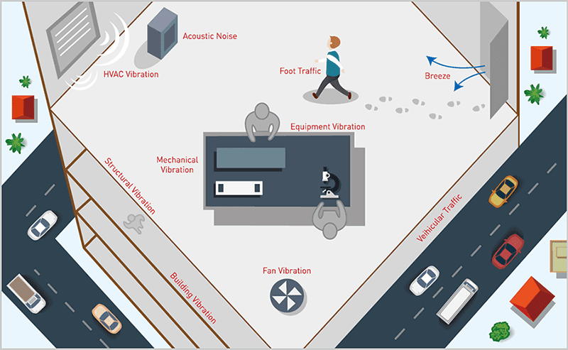
An electron microscope is not accepted for installation the way ordinary lab equipment is. Before a high-resolution SEM or TEM ships, the manufacturer requires the destination room to pass a site survey against its site-requirement document, and that survey examines four environmental factors: floor vibration, magnetic fields, acoustic noise, and temperature stability. A room that fails any one of them will hold the instrument below its specified resolution — no matter how carefully the other three were handled.
Each factor is measured, not estimated. Floor vibration is recorded as velocity spectra in one-third-octave bands at the exact proposed footprint. Magnetic fields are logged at column height in both AC and DC components. Acoustic noise is measured per frequency band with the building's mechanical systems running. Temperature is assessed for stability over time and for gradients across the room, together with the airflow the HVAC system delivers to the space.
The single most expensive mistake in electron microscopy facilities is sequencing: finishing the room first and surveying afterward. The workable order is the reverse — obtain the manufacturer's site-requirement document before the room design is frozen, survey the candidate location early, and let the measured gaps drive the design. This note walks through the four factors in that spirit: what the numbers mean, where rooms usually fail, and what can be fixed in place versus what argues for a different room. (For what an electron microscope is and how it forms images, see our companion introductory note.)
2.How Much Floor Vibration Is Acceptable?
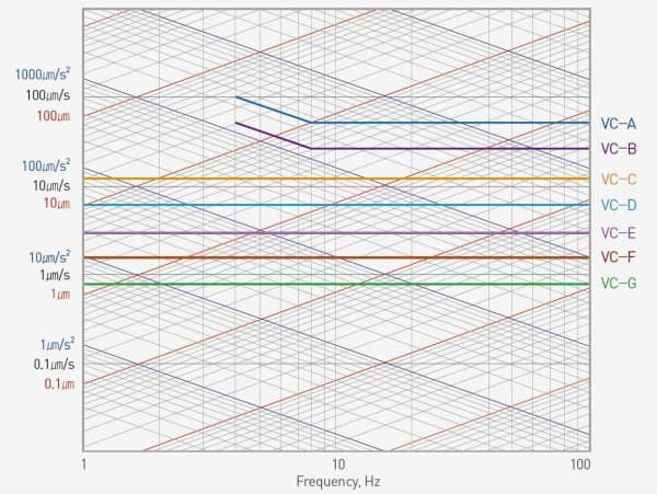
The vibration limits in vendor documents are commonly expressed against the generic vibration criterion (VC) curves — the industry's shared language for floor vibration, defined as RMS velocity limits in one-third-octave bands. In practice the survey lands on one of three curves. Imaging to roughly 1 μm detail puts the room at VC-C (12.5 μm/s); the bulk of SEM, TEM, and e-beam installations carry a VC-D specification (6.25 μm/s); and nanometer-scale work such as e-beam lithography pushes the room to VC-E (3.12 μm/s), a level few buildings meet without help. The microscope maker's own floor specification remains the contractual reference; the VC class is how facility engineers compare that specification against a real building.
Where the room sits in the building often decides the outcome before any measurement is taken. Vibration favors the lowest, stiffest ground available: a slab poured directly on grade, with mechanical rooms, loading docks, elevator shafts, and roads kept at a distance. Upper stories are a different physics problem — each suspended floor is its own resonant spring-mass system, moving most at the middle of a span and least where columns and shear walls stiffen it — so an unavoidable upper-floor installation belongs beside a column line.
And time the survey honestly. Floor vibration at two in the afternoon, with traffic moving and HVAC running, is the number that matters — a survey taken overnight can pass a room that fails every working day.
3.Magnetic Fields: The Invisible Dealbreaker
Stray magnetic fields deflect the electron beam directly, producing image shift and distortion that look like vibration but respond to none of the mechanical fixes. Vendor documents specify field limits at the column position, quoted in milligauss (mG) or microtesla (μT) — 1 mG equals 0.1 μT — and split into AC and DC components, with high-resolution instruments commonly allowing only fractions of a milligauss.
The usual sources are prosaic. Power distribution — mains wiring, feeder conduits, transformer and switchgear rooms — radiates 50/60 Hz AC fields that fall off quickly with distance, which is why a wall shared with an electrical room is a common and entirely avoidable siting error. Elevators combine both threats: the motor drive radiates AC fields, and the moving car is a multi-ton steel mass whose passage shifts the local DC field. Passing trucks, moving gates, and large steel doors do the same. Because these disturbances come and go, a magnetic survey must log over a full working day rather than sample a quiet moment.
Mitigation follows a fixed order: distance first (relocating the instrument or rerouting circuits), then active field-cancellation coils, then shielding of the room itself. One requirement is easy to overlook: everything that sits near the column must itself be magnetically quiet — including the vibration isolation platform directly beneath it. This is why DAEIL SYSTEMS' DVIA-ML platforms for electron microscopes are engineered to keep their own magnetic emission below 0.05 μT.
4.Acoustics and Airflow: The Overlooked Half of the Room Spec
Acoustic noise reaches the image by shaking what vibration isolation cannot protect: the column, its panels, and the detector hardware respond to airborne sound directly. Vendor acoustic limits are therefore frequency-dependent — specified per octave band, and hardest to satisfy in the low-frequency bands where building noise concentrates — a single dBA figure cannot demonstrate compliance.
In practice the loudest offenders are often the microscope's own support equipment: roughing pumps, water chillers, and compressors placed in the microscope room for convenience. The first acoustic fix is free — move them to an adjacent service room and pass the lines through the wall. HVAC comes next: low-velocity diffusers positioned so that no airstream blows on the column, since a direct draft is simultaneously an acoustic source and a thermal one. Temperature requirements in EM rooms are about stability more than setpoint — steady drift and small gradients matter more than hitting an exact number.
When the building cannot be quieted to specification, the enclosure approach brings the specification to the microscope instead. DAEIL SYSTEMS' DSE EM acoustic enclosure is an acoustic chamber designed specifically for electron microscopes: noise reduction of 18 dB at 80 Hz, 20 dB at 100 Hz, 40 dB at 200 Hz, and 50 dB at 1,000 Hz, effective across 3 Hz to 10 kHz, with a cooling control system to prevent temperature rise inside and a triple-paned window for monitoring without opening the door. For benchtop instruments — AFMs and compact electron microscopes — the tabletop DAE series applies the same broadband approach at bench scale.
5.When the Room Fails the Survey: What Can Be Fixed, and When to Move
Survey failures are not equal. The right response depends on which factor failed and in which frequency band.
Acoustic failures and vibration failures above roughly 10 Hz are usually correctable in place: relocate pumps and chillers, soft-mount what must stay, treat the HVAC path, and enclose the microscope if needed. AC magnetic failures from wiring are often correctable too, by rerouting circuits or adding field-cancellation coils. The genuinely stubborn cases are two. Large DC field transients from sources that cannot move — an elevator shaft on the other side of the wall, a route used by heavy vehicles — are the strongest argument for choosing a different room. And floor vibration below about 5 Hz cannot be fixed by any passive means: pneumatic isolators with natural frequencies of 1.2–3.0 Hz amplify rather than attenuate in exactly that band.
That low-frequency band is the specific territory of active vibration isolation, which measures floor motion and cancels it in real time. This is the territory DAEIL SYSTEMS' DVIA-ML was built for: an electron-microscope platform custom-sized per instrument up to 6,000 kg (DVIA-ML6000), whose control loop covers 0.5–200 Hz in all six degrees of freedom and takes out up to 80–90% of floor vibration at 1 Hz, rising to 90% or more from 2 Hz. Where the isolator should form the microscope's base itself, the base-type DVIA-MB covers 500–1,700 kg (MB1000), 1,500–3,500 kg (MB3000), and 3,000–6,000 kg (MB6000), isolating from 0.5 to 100 Hz with up to 50–80% attenuation at 1 Hz and 90% or more from 2 Hz. In practice, an active platform is what turns a failed survey on an upper floor into a compliant installation without moving the room.
6.Pre-Installation Checklist: Eight Items Before the Microscope Ships
The checklist below compresses this note into the sequence facility engineers actually follow. Every item is cheaper before the room is built than after.
1. Obtain the manufacturer's site-requirement document — vibration, magnetic, acoustic, temperature, floor loading, clearances — before the room design is frozen.
2. Commission a tri-axial floor vibration survey at the exact proposed footprint, during the worst realistic operating window, and compare it band by band against the required VC curve.
3. Log the magnetic environment in AC and DC components over a full working day, capturing elevator cycles, large-equipment movements, and switching events.
4. Measure acoustics per octave band with all building systems and the microscope's support equipment running.
5. Verify floor load capacity for the instrument plus any isolation platform, and walk the rigging path: door widths, corridor turns, ceiling heights.
6. Plan the room so pumps, chillers, and compressors sit in an adjacent service room, with only the lines penetrating the wall.
7. If any band below 5 Hz fails the vibration criterion, specify an active isolation platform sized from the survey data — not from a catalog.
8. Re-survey after fit-out and before acceptance: rooms change when walls, ducts, and equipment go in.
A specialist can compress steps 2 through 7 into a single visit. DAEIL SYSTEMS has supported electron microscope installations this way since 1984, with more than 1,000 documented installation case studies spanning SEM, TEM, and semiconductor metrology instruments.