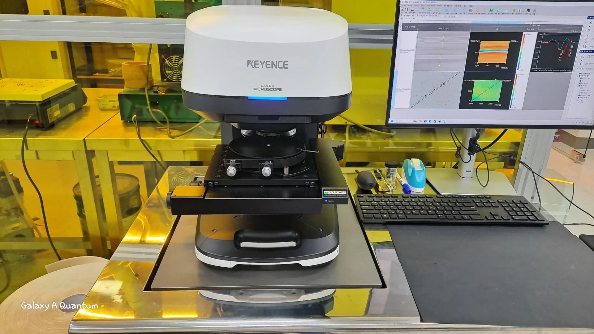
Robocube Tech DVIA-T87 (250922R2) Installation Report
Contents
Author
Engineer: Donggyu Park
Measurement Date
November 26, 2025
Report Written Date
December 1, 2025
Overview
Tuning and vibration measurements were conducted on the DVIA-T87 installed at the Robocube Tech assembly hall.
Measurements were conducted with equipment installed and in a Turned on/IDLE state.
Two items requested by the customer were checked: First, whether auto-leveling behaves normally such that posture is sustained when lifting the load; Second, whether the isolator attenuates vibrations effectively even when sizable vibration occurs. These checks were validated with vibration measurement hardware.
Intrinsic floor vibrations were relatively small; additional vibration input was supplied at the customer's request while measurements proceeded.
Measurement data are presented as VC curves, with Reference guidance for interpreting vibration levels.
Vibration Isolation Platform
Model: DVIA-T87
Serial number: 250922R2
Engineer
Donggyu Park, R&D Engineer, DAEIL SYSTEMS
Installation Site
Robocube Tech assembly hall
End User
Robocube Tech
Customer Equipment
Manufacturer: Robocube Tech
Equipment: 6-axis drive unit (internal review)
Model: N/A
Equipment Specification
-
Equipment Status
Equipment installed / Turned on/IDLE
Measuring Equipment
10.1) Brüel & Kjær LAN-XI DAQ Type 3050 DAQ
Hardware: B&K Front End Type 3050-A-040
Software: B&K Pulse Labshop 22 Version
10.2) Accelerometer
PCB Accelerometer
Model: 393B05
Vibration Measurement Setup
Bandwidth: 200 Hz
Lines: 3200
Averaging: Spectrum Averaging
Engineering Units: m/s
Window: Hanning
Overlap: Max
Conclusion
With the customer's equipment seated on the measurement location, isolator Auto-Leveling was confirmed to behave properly.
Across all axes, vibrations on the isolator top plate were observed to attenuate relative to the floor vibrations.
At measurement location 1, floor vibration Vertical at 63 Hz met VC-B, Left to Right at 25 Hz met VC-B, and Front to Back at 10 Hz met VC-A. On the isolator top plate, Vertical at 10 Hz exhibited VC-E, Left to Right at 16 Hz VC-E, and Front to Back at 10 Hz VC-B.
Auto-leveling qualification and vibration isolation measurements were jointly reviewed with the customer to close the inquiries.
Measurement Summary
| Place of Measurement | Status | Direction | Floor | DVIA-T87 |
|---|---|---|---|---|
| Robocube Tech assembly hall 1. Floor vibration 2. DVIA-T87 | Equipment installed / Turned on/IDLE | Vertical | VC-B @ 63 Hz | VC-E @ 10 Hz |
| Left to Right | VC-B @ 25 Hz | VC-E @ 16 Hz | ||
| Front to Back | VC-A @ 10 Hz | VC-B @ 10 Hz |
Data and Image
14.1) Measurement Data 1
Vertical VC Curves
(Red: floor vibration; Blue: DVIA-T87 top plane.)
Vertical Autospectrum
(Red: floor vibration; Blue: DVIA-T87 top plane.)
Vertical Transmissibility
(Red: floor vibration; Blue: DVIA-T87 top plane.)
Left to Right VC Curves
(Red: floor vibration; Blue: DVIA-T87 top plane.)
Left to Right Autospectrum
(Red: floor vibration; Blue: DVIA-T87 top plane.)
Left to Right Transmissibility
(Red: floor vibration; Blue: DVIA-T87 top plane.)
Front to Back VC Curves
(Red: floor vibration; Blue: DVIA-T87 top plane.)
Front to Back Autospectrum
(Red: floor vibration; Blue: DVIA-T87 top plane.)
Front to Back Transmissibility
(Red: floor vibration; Blue: DVIA-T87 top plane.)
Reference
Notes:
1. VC-A/B is measured in 1/3 octave bands from 8-80 Hz, VC-C through VC-G from 1-80 Hz.
2. Detail size refers to line widths in microelectronics manufacturing or particle sizes in medical research.
Share this Case Study
Case Study Information
Related Case Studies
Robocube Tech 6-Axis Actuator DVIA-T87 (260423R2) Installation Report
Pharrics BV MPI Corporation Probe Station MPI TS150 DVIA-T67 (260402R1) Installation Report