Hallym University JEOL JBX-8100F DVIA-PB2200 Installation Report
Contents
Overview
A first setup was performed on the DVIA-PB2200 installed at Hallym University (Chuncheon) before equipment placement.
The DVIA-PB2200 was connected to a PC to verify normal operation and installation via the UI Program.
Inspection was performed using vibration measurement equipment after tuning.
Written for internal retention; a tuning report was not requested.
System Information
Model: DVIA-PB2200 (DVIM-F-500 (2EA))
Serial Number: 220926R2
Engineer
Lee Young-ha (Manager), Chaewon Lee (Staff)
Installation Date
February 20, 2024
Location
한림대학교, C/R
Equipment
JEOL JBX-8100F
Number of Tuning Trial
1회차(장비 안착 전 튜닝)
Equipment Condition
장비 안착 전 상태
Measurement Device
9.1) Data Physics
Hardware: QUATTRO, Serial Number: 22436
Software: SignalCalc ACE
9.2) Measurement Setting
Bandwidth: 0 - 200Hz
Lines: 1600
Window: Hanning
Averaging: FFT Spectrum Averaging
Engineering Units: m/s
9.3) Accelerometer
PCB Accelerometer
Model: 393B05
9.4) Measurement Method
Accelerometers are attached to the top plate and floor for vibration measurement.
Vibration is measured in the Vertical, Left to Right, and Front to Back directions.
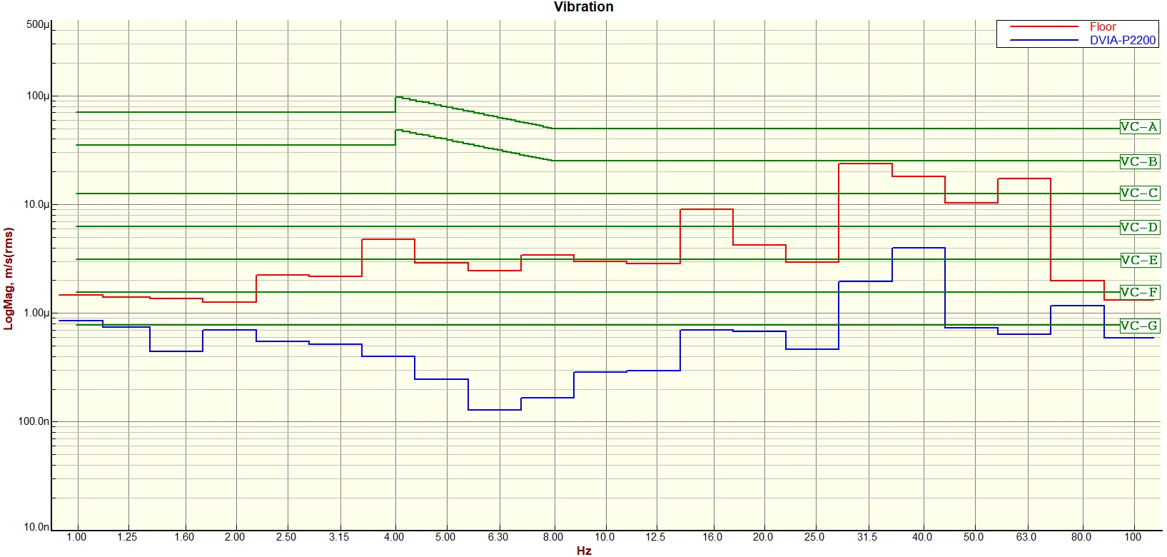
Measurement data are presented as VC Curve graphs.
Conclusion
Displacement sensor initial settings (Vertical: 1 mm, Horizontal: 3 mm) were configured correctly.
After float completion, displacement sensor float height (Vertical: 2.5 mm, Horizontal: 0 mm) and servo valve output operate normally.
With no load on the top, air cannot be supplied to the DVIM-F isolators inside the base platform.
Measurement after separating DVIM-F could not be performed due to internal air piping and unit cabling in the PB2200.
With no load on the PB2200 top and DVIM-F attached, outstanding passive and active performance cannot be demonstrated.
Summary of Vibration Results
Data and Image
Displacement Sensor and Servo Valve Output Check
Float On 이후 변위 센서 입력 값 확인
Float On 이후 Vertical 2.5 mm, Horizontal 0 mm으로 변위센서 값이 정상적으로 출력됩니다.
Float On 이후 Servo Valve 출력 값 확인
상부 장비 안착 전 상태에서의 Servo Valve의 출력이 약 1으로 모두 비슷한 출력을 보입니다.
Float On Displacement Sensor Input
Float On Servo Valve Output
UI Program Transmissibility
Passive Vertical Transmissibility
장비 안착 전으로 PB2200 위에 무게가 없고, DVIM-F Isolator로 체결되어 있어 9 Hz 이상에서 공진봉이 나타납니다.
Passive Left to Right Transmissibility
장비 안착 전으로 PB2200 위에 무게가 없고, DVIM-F Isolator로 체결되어 있어 17 Hz에서 공진봉이 나타납니다.
Passive Front to Back Transmissibility
장비 안착 전으로 PB2200 위에 무게가 없고, DVIM-F Isolator로 체결되어 있어 17 Hz에서 공진봉이 나타납니다.
Active Vertical Transmissibility
낮은 무게로 인해 FeedBack 튜닝 시 위상 마진을 위해 P Gain을 10 이하로 설정했습니다.
감쇠 형태는 유지되지만 제한적인 Gain 값으로 높은 성능을 출력할 수 없습니다.
Active Left to Right Transmissibility
낮은 무게로 인해 FeedBack 튜닝 시 위상 마진을 위해 P Gain을 10 이하로 설정했습니다.
감쇠 형태는 유지되지만 제한적인 Gain 값으로 높은 성능을 출력할 수 없습니다.
DVIM-F 체결 간섭 및 FeedForward 제어로 인해 20Hz에 공진봉이 나타납니다.
Active Front to Back Transmissibility
낮은 무게로 인해 FeedBack 튜닝 시 위상 마진을 위해 P Gain을 10 이하로 설정했습니다.
감쇠 형태는 유지되지만 제한적인 Gain 값으로 높은 성능을 출력할 수 없습니다.
DVIM-F 체결 간섭 및 FeedForward 제어로 인해 20Hz에 공진봉이 나타납니다.
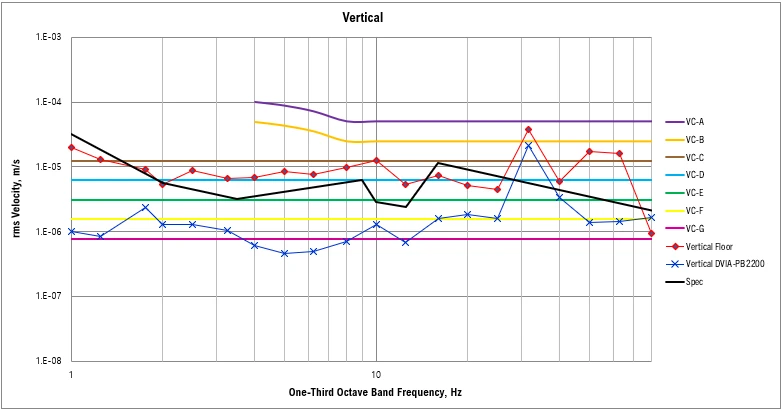
Vertical Floor VC Curve (rms Velocity, m/s)
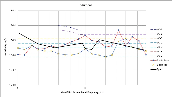
Vertical PB2200 VC Curve (rms Velocity, m/s)
무게가 없는 상태에서의 Servo Valve의 낮은 출력으로 주변 환경에 쉽게 영향을 받아 3 Hz 이하의 PB2200 진동이 증가합니다.
무게가 없는 상태에서의 FeedBack 제어의 악영향으로 20 Hz에서 진동이 증가합니다.
Left to Right Floor VC Curve (rms Velocity, m/s)
Left to Right PB2200 VC Curve (rms Velocity, m/s)
무게가 없는 상태에서의 FeedBack 제어의 악영향으로 12.5 Hz - 20 Hz에서 진동이 증가합니다.
Front to Back Floor VC Curve (rms Velocity, m/s)
Front to Back PB2200 VC Curve (rms Velocity, m/s)
무게가 없는 상태에서의 FeedBack 제어의 악영향으로 12.5 Hz - 20 Hz에서 진동이 증가합니다.
Reference
Generic Vibration Criteria
Notes:
1. VC-A/B is measured in 1/3 octave bands from 8-80 Hz, VC-C through VC-G from 1-80 Hz.
2. Detail size refers to line widths in microelectronics manufacturing or particle sizes in medical research.