Hallym University JEOL JBX-8100FS DVIA-PB2200 Installation Report
Contents
Overview
SET-UP was performed after equipment placement of the DVIA-PB2200 installed at Hallym University (Chuncheon).
Vibration from surrounding piping and equipment connected to the JBX-8100FS was significant, and SET-UP was performed with the equipment operating. This may affect DVIA-PB2200 performance.
After SET-UP completion, measurement data were plotted on VC Curve graphs.
Measurement date
24.04.04
Report written date
24.04.05
Vibration Isolation System Information
Model: DVIA-PB2200
Serial Number: 220926R2
Engineer
Park Jongwon and Chaewon Lee from DAEIL SYSTEMS
Installation date
April 2, 2024
Installation Site
Hallym University C/R,
End User
Hallym University
Customer Equipment
JEOL JBX-8100FS
Equipment vibration specification
Equipment Status
Equipment Operation
Tuning count
3rd tuning
Measuring Equipment
10.1) PULSE 22
-Hardware: Bruel & Kjaer Type 3050-A-040
-Software: LapShop Application (PULSE Lapshop)
10.2) Accelerometer
PCB Accelerometer
Model: 393B05
Measuring Set-up
11.1) Measurement setting
Bandwidth: 0 – 200 Hz
Lines: 801
Analyzer: FFT Spectrum Averaging
Signal Units: m/s2
Spectral Units: rms
11.2) Measurement method
Accelerometers are attached to the upper plate (DVIA-PB2200 top plate) and lower floor for vibration measurement.
Vibration is measured in Vertical, Left to Right, and Front to Back directions.
Conclusion
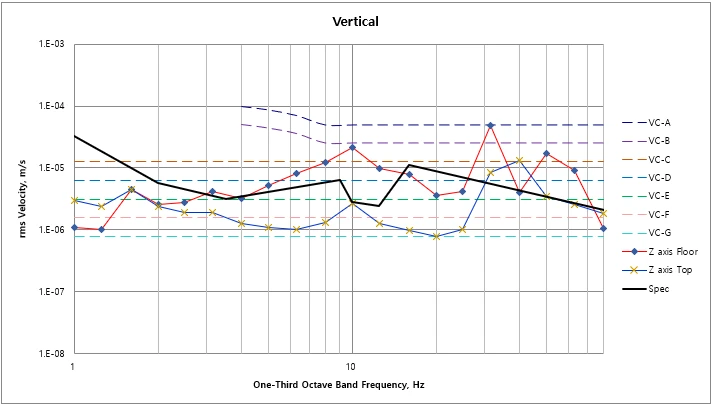
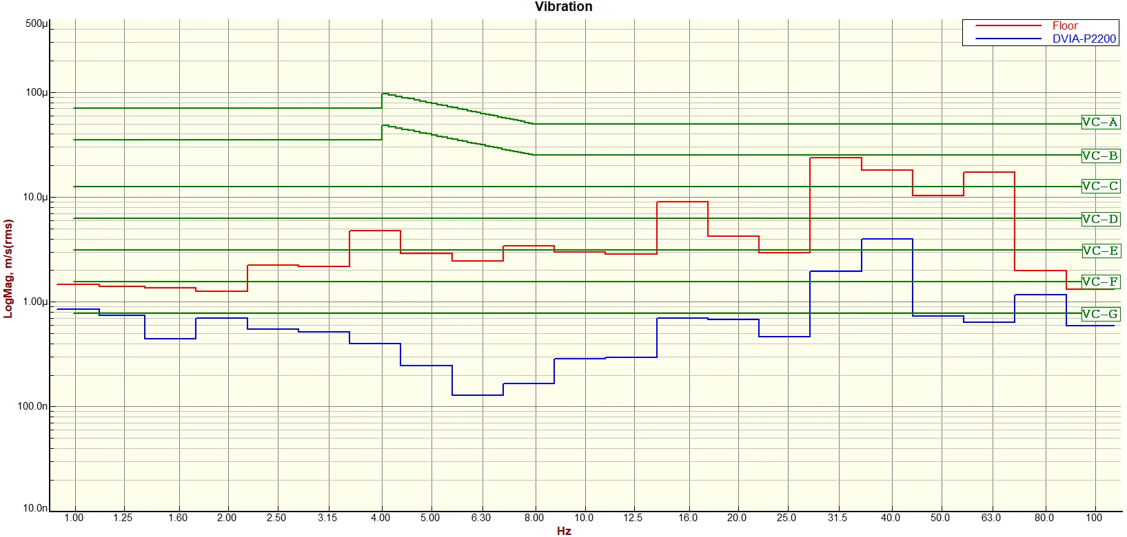
Vertical, Left to Right, and Front to Back measurement results all show rising vibration on the isolator top plate in the 30–40 Hz band. This is presumed to be vibration from equipment operation during measurement. Airflow from the cooler directed toward the isolator from the system control unit is also presumed to have a direct influence on the measured vibration.
Except for Vertical 30–40 Hz, all frequency bands satisfy the equipment vibration specification.
For accurate measurement of isolator performance, the E-beam equipment must be completely turned off.
Measurement Data
| Type | Position | Direction | Specification | Measurement | Result | ||
|---|---|---|---|---|---|---|---|
| Floor | DVIA-PB2200 | Floor | DVIA-PB2200 | ||||
| Vibration | C/R | Vertical | 3.25E-05 m/s - 5.66E-06 @ 1 Hz - 2 Hz | 9.21E-06 m/s @ 1.75 Hz | 2.39E-06 m/s @ 1.75 | ✗ FAIL | ✓ PASS |
| 5.66E-06m/s - 3.18E-06 @ 2 Hz – 3.5 Hz | 8.72E-06 m/s @ 2.5 Hz | 1.28E-06 m/s @ 2.5 | ✗ FAIL | ✓ PASS | |||
| 3.18E-06 m/s - 6.36E-06 @ 3.5 Hz - 9 Hz | 9.83E-06 m/s @ 8 Hz | 6.97E-97 m/s @ 8 Hz | ✗ FAIL | ✓ PASS | |||
| 6.36E-06 m/s – 2.83E-06 @ 9 Hz - 10 Hz | 1.27E-05 m/s @ 10 Hz | 1.29E-06 m/s @ 10 Hz | ✗ FAIL | ✓ PASS | |||
| 2.83E-06 m/s – 2.40E-06 @ 10 Hz – 12.5 Hz | 5.28E-06 m/s @ 12.5 Hz | 6.72E-07 m/s @ 12.5 | ✗ FAIL | ✓ PASS | |||
| 2.40E-06 m/s – 1.13E-05 @ 12.5 Hz - 16 Hz | 7.23E-06 m/s @ 16 Hz | 1.57E-06 m/s @ 16 Hz | ✗ FAIL | ✓ PASS | |||
| 1.13E-05 m/s – 1.70E-06 @ 16 Hz - 100 Hz | 3.70E-05 m/s @ 31.5 Hz | 2.12E-05 m/s @ 31.5 Hz | ✗ FAIL | ✗ FAIL | |||
| Left to Right | 3.25E-05 m/s - 5.66E-06 @ 1 Hz - 2 Hz | 4.22E-06 m/s @ 1 Hz | 1.88E-06 m/s @ 1 Hz | ✓ PASS | ✓ PASS | ||
| 5.66E-06m/s - 3.18E-06 @ 2 Hz – 3.5 Hz | 3.74E-06 m/s @ 2.5 Hz | 1.79E-06 m/s @ 2.5 Hz | ✓ PASS | ✓ PASS | |||
| 3.18E-06 m/s - 6.36E-06 @ 3.5 Hz - 9 Hz | 7.95E-07 m/s @ 8 Hz | 3.92E-07 m/s @ 8 Hz | ✓ PASS | ✓ PASS | |||
| 6.36E-06 m/s – 2.83E-06 @ 9 Hz - 10 Hz | 3.85E-07 m/s @ 10 Hz | 2.80E-07 m/s @ 10 Hz | ✓ PASS | ✓ PASS | |||
| 2.83E-06 m/s – 2.40E-06 @ 10 Hz – 12.5 Hz | 4.07E-07 m/s @ 12.5 Hz | 2.61E-07 m/s @ 12.5 Hz | ✓ PASS | ✓ PASS | |||
| 2.40E-06 m/s – 1.13E-05 @ 12.5 Hz - 16 Hz | 6.02E-07m/s @ 16 Hz | 4.61E-07 m/s @ 16 Hz | ✓ PASS | ✓ PASS | |||
| 1.13E-05 m/s – 1.70E-06 @ 16 Hz - 100 Hz | 4.17E-06 m/s @ 50 Hz | 1.05E-06 m/s @ 50 Hz | ✗ FAIL | ✓ PASS | |||
| Front to Back | 3.25E-05 m/s - 5.66E-06 @ 1 Hz - 2 Hz | 8.16E-06 m/s @ 1.75 Hz | 2.33E-06 m/s @ 1.75 Hz | ✗ FAIL | ✓ PASS | ||
| 5.66E-06m/s - 3.18E-06 @ 2 Hz – 3.5 Hz | 5.64E-06 m/s @ 2.5 Hz | 8.35E-07 m/s @ 2.5 Hz | ✗ FAIL | ✓ PASS | |||
| 3.18E-06 m/s - 6.36E-06 @ 3.5 Hz - 9 Hz | 3.42E-06 m/s @ 5 Hz | 3.23E-07 m/s @ 5 Hz | ✓ PASS | ✓ PASS | |||
| 6.36E-06 m/s – 2.83E-06 @ 9 Hz - 10 Hz | 1.86E-06 m/s @ 10 Hz | 3.77E-07 m/s @ 10 Hz | ✓ PASS | ✓ PASS | |||
| 2.83E-06 m/s – 2.40E-06 @ 10 Hz – 12.5 Hz | 3.91E-06 m/s @ 12.5 Hz | 5.91E-07 m/s @ 12.5 Hz | ✗ FAIL | ✓ PASS | |||
| 2.40E-06 m/s – 1.13E-05 @ 12.5 Hz - 16 Hz | 1.56E-06 m/s @ 16 Hz | 5.85E-07 m/s @ 16 Hz | ✓ PASS | ✓ PASS | |||
| 1.13E-05 m/s – 1.70E-06 @ 16 Hz - 100 Hz | 4.24E-06 m/s @ 63 Hz | 2.02E-06 m/s @ 63 Hz | ✗ FAIL | ✓ PASS |
Data and Image
Vertical VC Curves
Vertical Transmissibility
Left to Right VC Curves
Left to Right Transmissibility
Front to Back VC Curves
Front to Back Transmissibility
Reference
Generic Vibration Criteria
Notes:
1. VC-A/B is measured in 1/3 octave bands from 8-80 Hz, VC-C through VC-G from 1-80 Hz.
2. Detail size refers to line widths in microelectronics manufacturing or particle sizes in medical research.