YIMO China business trip report — DVIA-T65 service and DVIA-P4000 setup at Tier-1 Semiconductor (March 2023)
Contents
Report title and scope
YIMO Tech — China business trip report
Objectives: DVIA-T65(220210R1-1) inspection, repair, and vibration measurement; DVIA-P4000 setup and vibration measurement.
Trip metadata
| Field | Value |
|---|---|
| Authors | Hosang Yu, Youngha Lee |
| Trip dates | 2023.03.20 ~ 2023.03.24 |
| Report written date | 2023.03.27 |
| Date of business trip (form line) | 17.12.27~17.12.29 |
| Engineers | Hosang Yu (DAEIL SYSTEMS Production Dept. 2, Manager); Youngha Lee (DAEIL SYSTEMS R&D, Engineer) |
| DVIA-T65 location | YIMO Tech Office (Wuxi) |
| DVIA-P4000 location | Tier-1 Semiconductor (Wuxi) |
| Equipment above DVIA-T65 | TBD |
| Equipment above DVIA-P4000 | ASML eScan500 |
| Vibration measurement — PULSE 22 | Hardware: Bruel & Kjaer Type 3050-A-040; Software: LapShop Application (PULSE Lapshop) |
| Accelerometer | PCB Accelerometer Model 393B05 |
Trip work log
2023.03.20 (Mon) — Tool and parts check; China visa pickup (Giheung Hanatour); travel Incheon–Manila (transit).
2023.03.21 (Tue) — Transit to Shanghai Pudong; YIMO Tech TIM CHEN pickup and hotel; YIMO Tech Office; DVIA-T65(220210R1-1) repair and performance measurement (see §1).
2023.03.22 (Wed) — Tier-1 Semiconductor (Wuxi) site; P4000 passive unit air piping; controller and cable connection; floating / feedback / feedforward tuning; vibration measurement; cable-routing mitigation; tuning and measurement with equipment powered on; factory test comparison; IDE Active isolator confirmation; coordination calls; trip extension (see §2).
2023.03.23 (Thu) — Filter application tests; vibration data collection under multiple passive/active and measurement-point conditions (see §2).
1. DVIA-T65 (220210R1-1) repair and performance measurement
Symptoms: during auto leveling one of four springs did not rise after descending; all four springs rose during locking — limit switch damage suspected.
Repair: cover removed, limit switch inspected, damaged part replaced.
Limit switch damage
Tuning and performance measurement followed.
Z-axis Transmissibility
X-axis Transmissibility
Y-axis Transmissibility
Vibration measurement summary:
| Measurement Point | VC curves Z-axis (1-10 Hz) | Z-axis (12.5-80 Hz) | X-axis (1-10 Hz) | X-axis (12.5-80 Hz) | Y-axis (1-10 Hz) | Y-axis (12.5-80 Hz) |
|---|---|---|---|---|---|---|
| Floor | E | D | D | D | D | D |
| Active | F | G | F | G | F | G |
Z axis VC Curve
X axis VC Curve
Y axis VC Curve
Normal operation confirmed; unit reassembled.
2. DVIF-FA-P4000 (221227R2) setup and resonance investigation
Installation site: Tier-1 Semiconductor (Wuxi). Passive P4000 unit air piping connected; controller placed and cables connected; floating, feedback, and feedforward tuning performed.
With ASML equipment powered on, clean phase and transmissibility plots were not obtained; resonance above 0 dB occurred between 10~20 Hz.
Resonance observation plot
Feedforward – Z axis (initial tuning)
Feedforward – X axis (initial tuning)
Initial vibration measurement (2023.03.22):
Z axis
X axis
Y axis
Vibration results showed top-plate levels larger than floor in the 10~25 Hz band.
Cable routing fixed above the ASML tool was judged to reduce actuator control force; bolts were removed and supports placed under the routing without interfering with the ASML tool. Resonance near 20 Hz remained after retuning.
Cable routing site
Cable routing detail
With equipment power on, the customer declined power cycling (estimated 5~7 days). Without pre-installation first-stage tuning, 20 Hz resonance could not be attributed solely to equipment vibration or a structural resonance mode; factory test did not show the symptom — product defect was ruled out.
Factory Test results (221227R2_Factory Test_23.01.28)
Z axis
X axis
Y axis
An IDE Active isolator stack above the tool was confirmed.
IDE Active Isolator location
Prior internal testing of active-on-active stacks noted feedforward/feedback conflicts and oscillation risk; SHOWA and Daeil Systems concluded the arrangement unsuitable (reference: M-type multi-stage isolator performance test document).
Multi-stage isolator reference
YIMO Tech requested maintaining the installed environment (IDE + TMC isolators) for future order evaluation while seeking resonance reduction.
2023.03.23 — Lead/lag and lowpass filters did not reduce the ~20 Hz peak; raising feedback gain increased the peak; tuning focused on lowering feedback gain.
Feedback gain tuning plot
Feedforward – Z axis (filter test day)
Feedforward – X axis (filter test day)
Morning — P4000 passive, P4000 top plate to IDE isolator top plate:
Z axis
X axis
Y axis
P4000 active, P4000 top plate to IDE isolator top plate:
Z axis
X axis
Y axis
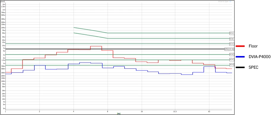
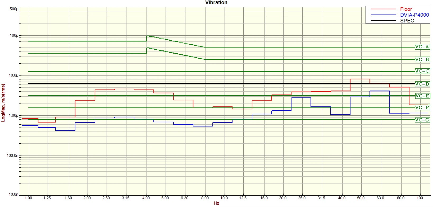
Afternoon — P4000 passive, floor to P4000 top plate:
Z axis
X axis
Y axis
P4000 passive, P4000 top plate to IDE isolator top plate (afternoon):
Z axis
X axis
Y axis
P4000 active, floor to P4000 top plate:
Z axis
X axis
Y axis
P4000 active, floor to IDE isolator top plate:
Z axis
X axis
Y axis
Morning vs afternoon IDE active isolator top/bottom data differed; ASML engineer operation during afternoon work suggested IDE isolator active only during tool operation.
Conclusions
DVIA-T65(220210R1-1) repair and performance measurement
Limit switch was damaged and replaced; performance normal.
DVIF-FA-P4000-2800x1450x600H(221227R2) setup and resonance mitigation
At the ASML equipment measurement plane (above IDE Active isolator), vibration results met equipment spec: Z-axis VC-G; X- and Y-axis VC-E — sufficiently satisfying the VC-D equipment requirement.
The DVIA-P4000 ~20 Hz peak (structural resonance) was not resolved. With upper equipment powered on, root cause could not be judged definitively; factory test and installed equipment environment / equipment natural frequency are the likely contributors. For future DVIA-P4000 orders with the same ASML tool, first-stage tuning before equipment installation is recommended.
Two-stage active products (P4000 + IDE Active isolator) were installed. YIMO TECH did not identify upper active isolation before installation completed; active presence was recognized during setup. ASML engineers appeared to activate IDE isolator only during tool operation; resonance also occurred with IDE off — upper active isolator was judged not to be the sole cause. No oscillation was observed despite two-stage active use. Further study with SHOWA on two-stage active stability and resonance is planned.
IDE Active information
Active: IDE-ATAN module series — ATAN100, ATAN300, ATAN500.
ATAN-100 load: 600 kg ~ 1800 kg; ATAN-300 load: 1000 kg ~ 2500 kg; ATAN-500 load: 2000 kg ~ 6000 kg.
Active product applied on ASML equipment: ATAN-300 estimated.
IDE ATAN module series
ATAN-300 load range (estimate for ASML tool)
Share this Case Study
Case Study Information
Related Case Studies

Hua Hong Semiconductor (Wuxi) ASML eScan500 DVIA-P4000 (221227R2) Installation Report
YIMO Huahong FAB 9 ASML E-beam Wafer inspection system eScan460 DVIA-P4000 Installation Report