Installation Report
DVIA-M Series
08-25-2023
Thermo Fisher Scientific Talos F200X G2 TEM DVIA-MB3000 Installation Report
DVIA-M Series
Installation Report
Thermo Fisher Scientific
Contents
Executive Summary
Introduction
The purpose of this work is to install the Vibration Isolation MB 3000 system for the Thermo Fisher Scientific Talos F200X at the University of North Dakota Grand Forks. Thermo Fisher Scientific hired VEC to install the field cancellation system and provide a report of the completed work.
Summary Results
Below is a summary of the results:
- MB3000 ON PASSED the Vibration specifications
Product Details
| Part Delivered | Serial Number | Software |
|---|---|---|
| MB3000 | 221104R3 | Site-Specific Tune |
Summary of Work
We installed the system by
- Positioning the Daeil under the microscope
We tested the system by
- Creating and uploading a site specific tune
- Collecting vibration data to verify the performance
We left the system
- In position and turned on.
Procedures
Vibration
VEC conducted vibration measurements in six directions. Acceleration measurements were taken at a bandwidth of 200 with units of um/s (RMS). The acceleration spectra with 200 bandwidths were recorded.
Setup
| Vibration | |
|---|---|
| Bandwidth | 200 |
| Lines | 1600 |
| Window | Hanning |
| Coupling | ICP 2mA |
| Average Type | Stable |
| Duration | 60 |
| Engineering Units | um/s (RMS) |
Vibration
VEC conducted vibration measurements in three directions. Acceleration measurements were taken at a bandwidth of Hz with units of um/s. The acceleration spectra with Hz bandwidths were recorded.
Setup
| Part Delivered | |
|---|---|
| Bandwidth | Hz |
| Duration | seconds |
| Engineering Units | um/s |
Specifications
VEC used the following specifications for the project.
Specification Summary
| Tool | Specification |
|---|---|
| Thermo Fisher Scientific Talos F200X | Vibration X & Y: VC-F 1.56 um/s 1Hz - 100Hz Z: VC-E 3.12 um/s 1Hz - 100Hz |
Detailed Specifications
Figure 1
: Thermo Fisher Scientific Talos F200X – Vibration Specification
5.4.1 VC Curves for System Enclosure
| System | Vertical | Left to right | Front to back |
|---|---|---|---|
| Talos F200X,S; TEM info limit 0.12nm | E | F | F |
| Talos F200X,S; STEM res. 0.16nm | E | F | F |
| Talos F200C; TEM info limit 0.15nm | E | F | F |
| Talos F200C; STEM res. 0.20nm | E | F | F |
Thermo Fisher Scientific Talos F200X – 1 Vibration Specification; In general VC-F should be achieved.
Figure 1: Thermo Fisher Scientific Talos F200X – Vibration Specification
Vibration criteria:
| Criterion | Description |
|---|---|
| VC-E | • Floor ≥ 700 kg/m², indication > 29 cm thick • Rigid support structure with small spans or heavy foundation plate • Zone VC-E separately founded, keep around by dilation free of residual building • Technical rooms, elevators, stairways and circulation areas outside dilated zone VC-E • At the location of the dilatation disconnect channels and pipes to prevent transmission of vibration. No vibration sources in zone VC-E • Technical rooms on distance, isolate vibration sources outside zone VC-E • Zone VC-E on ground floor or 1st floor |
| VC-F | • Floor ≥ 1,000 kg/m², indication > 58 cm thick, heavy foundation plate • Zone VC-F separately founded, keep around by dilation free of residual building • Technical rooms, elevators, stairways and circulation areas outside dilated zone VC-F • At the location of the dilatation disconnect channels and pipes to prevent transmission of vibration • No vibration sources in zone VC-F • Technical rooms on distance, isolate vibration sources outside zone VC-F • Zone VC-F on ground floor |
Results
Summary Results
Below is a summary of the results:
- MB3000 PASSED the Vibration specifications
Detailed Results
| Type | Position | Direction | Specification | Measurement | Result |
|---|---|---|---|---|---|
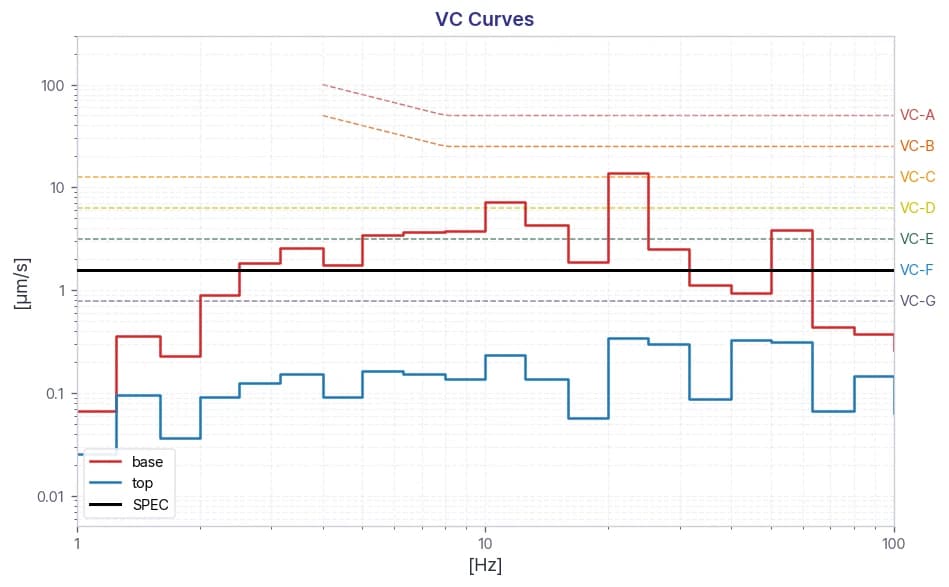
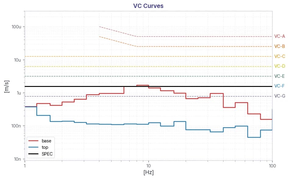
| Vibration | Floor | X-Axis (VC-F) | 1.56 um/s 1Hz - 100Hz | 1 um/s @ 63 Hz | ✓ PASS |
| Y-Axis (VC-F) | 0.515 um/s @ 63 Hz | ✓ PASS | |||
| Z-Axis (VC-E) | 3.12 um/s 1Hz - 100Hz | 3 um/s @ 63 Hz | ✓ PASS | ||
| Isolators | X-Axis (VC-F) | 1.56 um/s 1Hz - 100Hz | 0.08 um/s @ 63 Hz | ✓ PASS | |
| Y-Axis (VC-F) | 0.107 um/s @ 3 Hz | ✓ PASS | |||
| Z-Axis (VC-E) | 3.12 um/s 1Hz - 100Hz | 0.133 um/s @ 32 Hz | ✓ PASS |
Data
Thermo Fisher Scientific Talos F200X
Vibration
Figure 2: Ground X-Axis
Figure 3: Ground Y-Axis
Figure 4: Ground Z-Axis
Figure 5: Isolators X Axis
Figure 6: Isolators Y Axis
Figure 7: Isolators Z Axis
Figure 8: Transmissibility X Axis
Figure 9: Transmissibility Y Axis
Figure 10: Transmissibility Z Axis
Reference
Generic Vibration Criteria
Notes:
1. VC-A/B is measured in 1/3 octave bands from 8-80 Hz, VC-C through VC-G from 1-80 Hz.
2. Detail size refers to line widths in microelectronics manufacturing or particle sizes in medical research.
Share this Case Study
Case Study Information
Category
Installation Report
SeriesDVIA-M Series
Date08-25-2023
Tags
DVIA-M Series
Installation Report
Thermo Fisher Scientific
Related Case Studies
DVIA-M Series
YIMO TECH Thermo Fisher Scientific Apreo 2S SEM DVIA-ML1000 Installation Report
07-15-2026Read more

DVIA-M Series
YDRICQS Thermo Fisher Scientific Helios 5CX FIB-SEM DVIA-ML1000 Installation Report
07-06-2026Read more
DVIA-M Series
BIEL Crystal Thermo Fisher Scientific Helios 5 FIB-SEM DVIA-ML1000 Installation Report
07-04-2026Read more