Thermofisher Scientific Apero 2 SEM DVIA-MB1000 Installation Report
Contents
1. Measurement Details
Measurement Date: September 5, 2017
Measurement Devices:
LAN-XI Data Acquisition Hardware – Brüel & Kjær 3050-A-040 (Serial Number: 3050-111438)
Data Analysis Software – Brüel & Kjær PULSE LAB SHOP 22
Sensors – PCB Accelerometer Model: 393B05 (Serial Number: 48995, 40626)
Measurement Location: 1st Floor
Measurement Setup:
Bandwidth: 0 – 100 Hz
Lines: 400
Window: Hanning
Averaging: Fast Fourier Transform Spectrum Averaging
Amplitude Units: m/s²
Spectral Unit: RMS
2. Equipment Information
Manufacturer: Thermofisher Scientific
Model: Apero 2
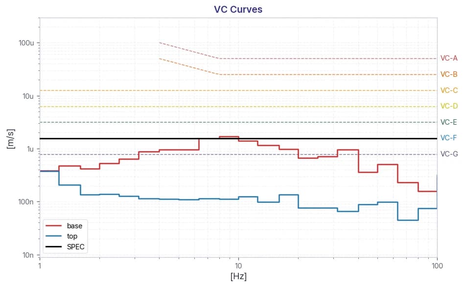
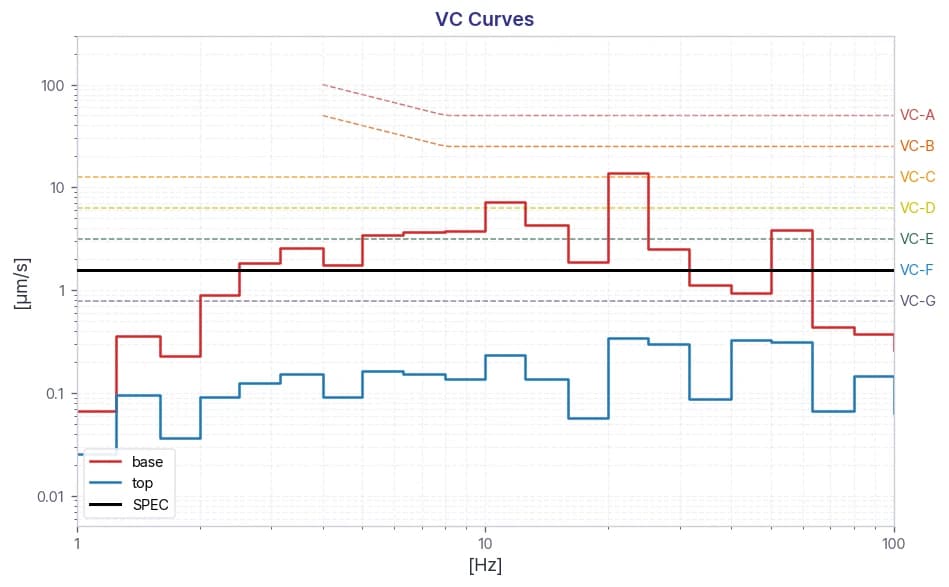
Floor Vibration Specification: VC-F (in general)
Disturbances due to vibrations and acoustics play a significant role. Vibration levels can be limited by proper building design in combination with vibration isolated platforms.
The floor vibrations are defined by the vibration criterion (VC) curves, by Ungar and Gordon. VC levels are defined as rms speed values, integrated over one
third octave bands. The VC-curves are to be used as guidelines only, the final room behavior with regard to vibrations will be determined during a site survey performed by trained FEI personnel using FEI’s Site Evaluation Tool. Depending the purpose of the microscope, time constant is involved in the vibration characteristics. VC Curves Guidelines provided by the VC-curves can be interpreted as described below.
The table lists applicable VC-curves for certain direction and system. In general VC-F should be achieved.
3. Vibration Isolation System Information
Model: DVIA-MB1000
| Specification | Value |
|---|---|
| Platform Dimensions | 1140 x 910 x 224 mm |
| Load Capacity | 500 - 1700 kg |
| Actuator | Electromagnetic Actuator |
| Maximum Actuator Force | Vertical: 40N, Horizontal: 20 N |
| Degrees of Freedom | 6 degrees |
| Active Isolation Range | 0.5 - 100 Hz |
| Vibration Isolation at 2 Hz | ≥90% |
| Vibration Isolation at 10 Hz | ≥99% |
| Input Voltage | AC100 - 240V / 50 - 60 Hz / 1A |
| Power Consumption | Maximum 110W, <50 W in normal operation |
| Operating Temperature | 5 - 50 °C |
| Operating Humidity | 20 - 90% |
| Required Air Pressure | ≥ 0.5 MPa (5 bar) |
4. Installation Photos
5. Summary
| Item | Z axis (Vertical) | X axis (Left to Right) | Y axis (Front to Back) |
|---|---|---|---|
| Frequency Range | 1 - 80 Hz | 1 - 80 Hz | 1 - 80 Hz |
| Floor Vibration Specification | VC-F | VC-F | VC-F |
| Floor Vibration | ✗ Fail | ✗ Fail | ✗ Fail |
| Vibration on AVIS | ✓ Pass | ✓ Pass | ✓ Pass |
6. Results
Z-axis (Vertical)
X-axis (Left to Right)
Y-axis (Front to Back)
7. Results – Vibration Isolation Effects on Imaging
8. Reference
Generic Vibration Criteria
*Notes:*
1. As measured in one-third octave bands over 8-80 Hz (VC-A/B) or 1-80 Hz (VC-C through VC-G).
2. Detail size refers to width in microelectronics fabrication or particle size in medical research.
Share this Case Study
Case Study Information
Related Case Studies
YIMO TECH Thermo Fisher Scientific Apreo 2S SEM DVIA-ML1000 Installation Report

YDRICQS Thermo Fisher Scientific Helios 5CX FIB-SEM DVIA-ML1000 Installation Report