Hitachi SEM SU3500 DVIA-MB1000 (MB1000 P12) China business trip worksheet — 2016.04.08
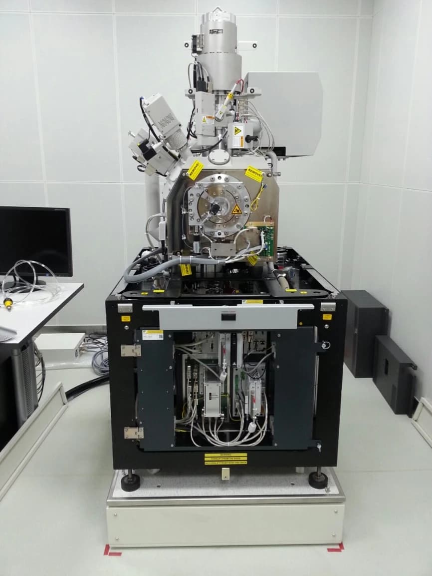
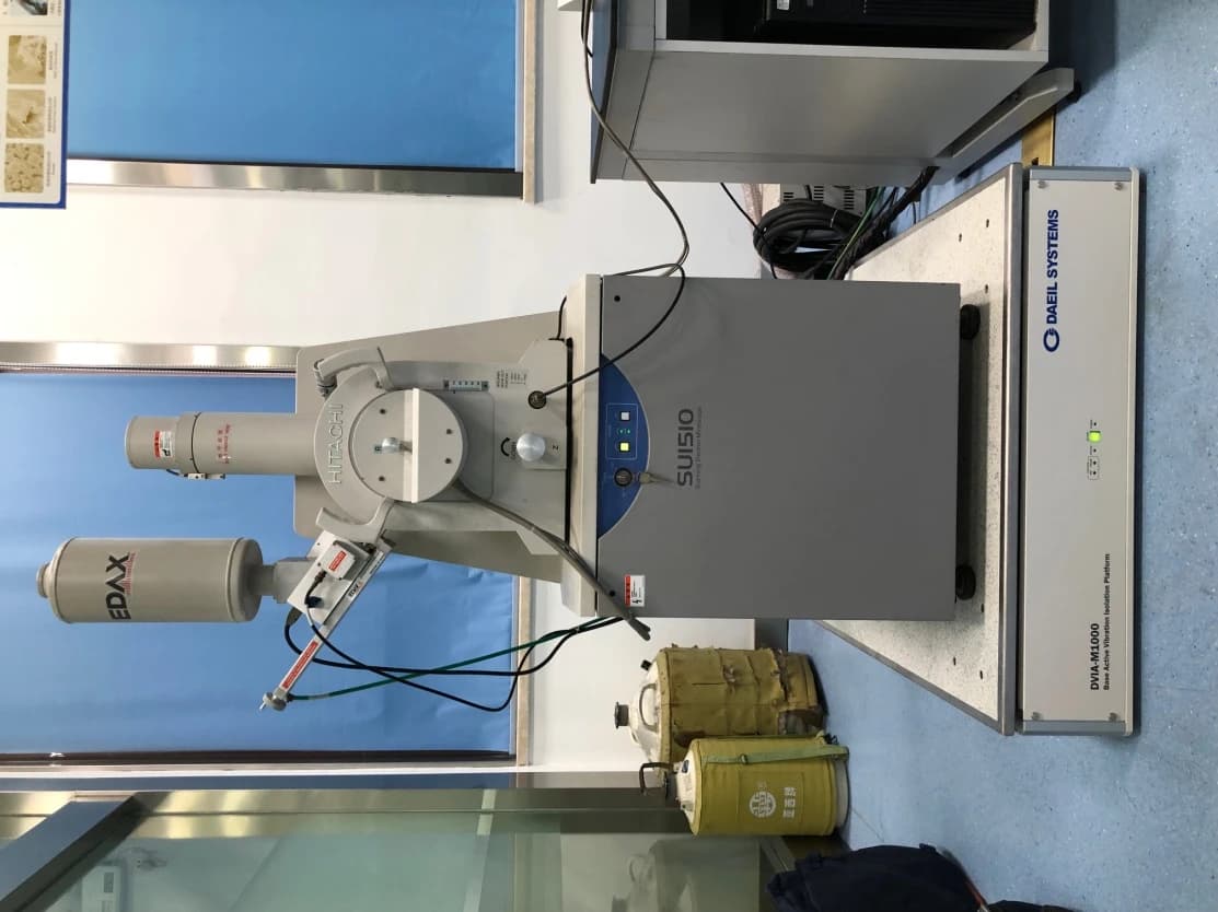
Equipment picture
Target equipment
SU3500 ( HITACHI SEM )
Place of installation
N/A
Remark
N/A
END USER
N/A
Travelers / Business trip dates
Choi, Hyoung Mun, Lim, Jong-wook / 16.04.05 ~ 16.04.07
Date of reporting
2016.04.08
Business trip schedule
16.04.05
Depart and arrive at the installation site
Passive setup (cable dressing)
16.04.06
Active setup
Review equipment images
Measure the vibration environment and support the customer
16.04.07
Consultation on installation solutions for JEOL 2100F and FEI TEM equipment
Return
Summary of installation results
| Condition | Test Direction | Base | Top |
|---|---|---|---|
| ACTIVE | Z | C | G |
| X | C | F | |
| Y | D | G |
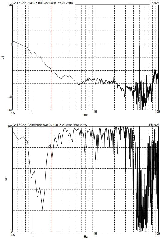
Good omnidirectional performance. (See Attachment 1.)
Floor vibration environment measured as vertical C-Class; horizontal X as C-Class and horizontal Y as D-Class.
On the active isolation top surface, vertical is G-Class and horizontal X is F-Class and Y is G-Class, with good overall performance. (See Attachment 2.)
Equipment images were captured to confirm isolation behaviour. (See Attachment 3.)
The customer is highly satisfied.
Coordination with NEMO on the Active installation was carried out. (See Attachment 4.)
MB1000 internal program performance measurement result
Z axis
X axis
Y axis
Vibration environment measurement results
Z axis
X axis
Y axis
Equipment measurement results (SEM imaging)
OFF
ON
Attachment 4 — Active consultation
JEOL 2100F solution
The installation location is on an access floor.
DAEIL, YIMO, and the end user will coordinate to carry out floor civil work.
Outcomes from coordination with NEMO during the China visit (04/07) are as follows:
⇒ In Figure 1, the blue/teal boxes denote the overall footprint including the equipment and desks; the red box is the area requiring isolation.
⇒ The team will propose installing DAEIL MB1000 within the red-box area in Figure 1, or alternatively installing with a support frame and isolation platform as illustrated in Figure 2, depending on the customer’s preference, with further coordination to follow.
JEOL 2100F proposal diagram (discussion)
Figure 1 — JEOL 2100F layout
FEI TEM
Figure 3 shows the TMC solution; the customer wants a frame of that form.
Following discussion with NEMO, the team will propose fabricating a frame as in Figure 4 (red outline) to the customer.
Input from the design team will be required.
Figure 4 — DAEIL SOLUTION
Figure 3 — TMC SOLUTION
Share this Case Study
Case Study Information
Related Case Studies
Wenzhou Hongfeng Electric Alloy Hitachi SU1510 MB1000 (P141) China trip installation report — 2019
Zhejiang University Hitachi SU8010 DVIA-MB1000 (P68) MB1000 program worksheet — 2018.09.17