Active vs. Passive Vibration Isolation: How to Choose
Transmissibility intuition, damping trade-offs, and a floor-survey decision checklist for choosing active or passive vibration isolation in labs and fabs.
Last updated
1.Why Every Spring Amplifies at Resonance
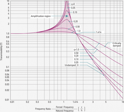
Every passive isolator — pneumatic, elastomeric, or coil spring — is a mass suspended on a compliant element, and its behavior is captured by a single curve: transmissibility, the ratio of platform motion to floor motion at each frequency. Well below the natural frequency, the payload simply rides the floor and transmissibility is essentially 1. Far above it, the payload cannot keep up with the rapid floor motion, and transmissibility falls steeply. Between the two sits the problem: at the natural frequency, transmissibility rises above 1. The isolator makes the vibration worse.
The energy argument explains why this is unavoidable rather than a design defect. At resonance, the floor input arrives in phase with the platform's velocity on every cycle. The spring stores the incoming energy and returns it at exactly the rate the suspended mass naturally oscillates, so each cycle deposits net energy into the system. Displacement grows until the power dissipated by damping equals the power injected by the floor. An ideal undamped spring would let the amplitude grow without bound; a real isolator settles at a peak that can be several times the floor input.
Pneumatic isolators in the DVIM class achieve natural frequencies of roughly 1.2–3.0 Hz. That places the amplification band squarely in the region where building sway, wind loading, and heavy traffic concentrate their energy — and useful passive isolation typically begins only above about 5–10 Hz.
2.The Damping Trade-Off: Flatten the Peak, Lose the Roll-Off
The textbook fix for the resonance peak is damping, and it works — up to a point. Adding a damper gives the system a way to dissipate the energy the spring keeps recycling, so the peak flattens. But the damper is itself a mechanical connection between floor and payload, and above resonance that connection becomes the dominant transmission path.
The math makes the trade-off explicit. A lightly damped isolator rolls off with the square of the frequency ratio: double the frequency, quarter the transmitted motion. A heavily damped isolator rolls off only in proportion to the frequency ratio, because the damping force — proportional to relative velocity — grows with frequency and keeps feeding floor motion into the payload. Flatten the peak at 2 Hz and you pay for it at 20, 50, and 100 Hz, exactly where a passive system should be doing its best work.
Passive design is therefore always a compromise: enough damping to survive resonance without excessive amplification, little enough to preserve high-frequency isolation. Active control breaks the compromise. Velocity feedback from sensors on the isolated platform lets a DSP apply a damping force referenced to inertial space rather than to the moving floor — the resonance peak is suppressed electronically, with no physical damper coupling floor vibration into the payload at high frequency. This is the core reason an actively controlled platform can isolate from 0.5 Hz without giving anything back above 10 Hz.
3.Reading the Floor Survey: A Decision Checklist
The active-versus-passive decision should never be made from a catalog; it should be made from a measured floor spectrum. A site survey with a seismic-grade sensor produces a velocity spectrum, usually plotted in one-third-octave bands against the VC criterion curves (VC-A through VC-G) that instrument makers use to specify allowable floor vibration.
Once the spectrum is in hand, the logic is mechanical.
Dominant peaks below 5 Hz. Building sway, wind response of upper floors, and nearby heavy traffic typically show up here. A passive isolator with a 1.2–3.0 Hz natural frequency will amplify part of this band and barely attenuate the rest. If the instrument's target — say VC-C or better — is violated below 5 Hz, active isolation is the only mechanism that removes energy there.
Energy concentrated above 10 Hz. Pumps, air handlers, and machinery harmonics usually dominate above 10 Hz. This is well inside the passive isolation band; a properly loaded pneumatic system attenuates it strongly, and adding active control buys little.
Mixed spectra. Compare each band against the required VC curve and compute the attenuation needed per band. If low-frequency deficits exist at all, choose active — an active system also covers the high band (the DVIA-ML operates from 0.5 to 200 Hz), while the reverse is never true.
Finally, account for variability: a survey taken at night can miss daytime traffic peaks, so measure during the worst realistic operating window.
4.What Active Control Actually Changes
An active platform replaces the passive compromise with a measurement-and-cancellation loop. In DAEIL SYSTEMS' DVIA architecture, feedback and feedforward run together. Geophone velocity sensors on the isolated platform (2.55 V/in/s, roughly 100.4 V/m/s sensitivity) feed a DSP that drives electromagnetic actuators, with loop response under 0.5 ms on some models. Feedforward sensors on the floor measure incoming ground vibration and command a cancelling force before the disturbance reaches the payload. Control acts in all six degrees of freedom — three translations and three rotations — because floor vibration never arrives conveniently along a single axis.
The measurable result on the DVIA-ML platform: isolation effective from 0.5 Hz, up to 80–90% attenuation at 1 Hz, and 90% or better from 2 Hz upward, with bandwidth extending to 200 Hz. For electron-microscope installations, where stray fields matter as much as vibration, the ML series keeps magnetic emission below 0.05 μT. Payload capacity reaches 6,000 kg on the DVIA-ML6000 — enough for a full TEM column with its base.
One architectural note: not every DVIA model is electromagnetic. The clean-room DVIA-P uses accelerometers and pneumatic servo actuators on the same closed-loop principle — an active-pneumatic approach suited to semiconductor metrology tools such as CD-SEM, DR-SEM, and photomask inspection systems, where payloads are large and fab utilities are already in place. A model-level comparison of the lineup is maintained on our active vibration isolation systems page.
| Parameter | Passive pneumatic | Active (feedback + feedforward) |
|---|---|---|
| Natural frequency | 1.2–3.0 Hz | Not set by suspension stiffness — actively controlled |
| Isolation begins | approx. 5–10 Hz | 0.5 Hz |
| At 1 Hz | No isolation — amplifies near resonance | up to 80–90% |
| Above 2 Hz | Improves with frequency | above 90% |
| Control bandwidth | Passive — none | 0.5–200 Hz |
| Degrees of freedom | Passive support | 6 DOF sensed and driven (X, Y, Z, θx, θy, θz) |
| Magnetic emission | None (no actuators) | Below 0.05 μT (DVIA-ML) |
| Loop response | Not applicable | Under 0.5 ms (some models) |
Every isolation figure is stated with the frequency at which it applies. A percentage quoted without a frequency cannot be compared between vendors.
5.Cost and Complexity: An Honest Accounting
Passive isolation earns its place through simplicity. A pneumatic isolator or optical table has no control electronics, draws no power, and needs no commissioning beyond leveling and load balancing. There is nothing to configure and very little to fail. For a laser table in a photonics lab on a quiet slab, a DVIO optical table or DVID workstation is often the correct answer — not merely the budget answer.
Active systems cost more, and the cost is not only the purchase price. They need electrical power, a commissioning procedure, and a payload within the design envelope. Those are real considerations, and a vendor who skips past them is optimizing for the order rather than the installation.
The honest framing is that the two technologies are not competing on the same axis. Passive buys attenuation above roughly 5–10 Hz at minimal complexity. Active buys the band below 5 Hz — the band passive physics cannot reach — plus suppression of the resonance peak itself, at the price of electronics and setup. If your floor survey shows no deficit below 5 Hz, buying active means paying for capability you will not use. If it shows a deficit at 1–3 Hz, no amount of passive spending will close it: softer springs lower the natural frequency but deepen the resonance problem, and heavier damping trades away the high-frequency performance you already had.
6.Hybrid Deployments: Where Each Technology Belongs in One Lab
Most facilities do not choose one technology; they zone. The instruments that resolve nanometers get active platforms, and everything else rides passive supports.
A typical electron-microscopy suite: the SEM or TEM sits on a DVIA-ML custom platform (or DVIA-MLP in Thermo Fisher SEM configurations), sample-preparation benches use DVID passive workstations, and interferometers or laser optics elsewhere in the lab sit on DVIO optical tables over DVIM pneumatic isolators. Benchtop instruments — compact AFMs, high-magnification optical microscopes — take a DVIA-T tabletop unit where a full platform is unwarranted. In semiconductor fabs, DVIA-P active-pneumatic systems go under CD-SEM, DR-SEM, and photomask inspection tools, while surrounding metrology benches remain passive. Where an instrument needs point isolation rather than a full platform, modular DVIA-ULF isolators support SEM, AFM, and laser installations; OEM builders integrate the DVIA-M module inside their own tools.
The zoning logic follows directly from the earlier sections: spend the control loop where the floor spectrum violates the instrument's VC requirement in the low band, and let unpowered isolation carry the rest of the room. This also simplifies operations — fewer powered systems to commission and maintain — and concentrates budget where it changes image quality. A survey-first, zone-second approach almost always yields lower total cost than uniformly specifying either technology across the lab.